Extrusion type modified starch grinding device
A modified starch, extrusion technology, applied in the direction of grain processing, etc., can solve the problems of affecting production efficiency, unable to collect modified starch in time, etc.
- Summary
- Abstract
- Description
- Claims
- Application Information
AI Technical Summary
Problems solved by technology
Method used
Image
Examples
Embodiment 1
[0065] An extruding modified starch crushing device, such as figure 1 As shown, the first fixed plate 1, the first supporting plate 2, the first discharging frame 3, the pressing mechanism 4 and the pushing mechanism 5 are included, the right side of the first fixed plate 1 is provided with the first supporting plate 2, the first A support plate 2 is provided with a first discharge frame 3 , a pressing mechanism 4 is provided between the front and rear sides of the first discharge frame 3 , and a push mechanism 5 is provided on the left side of the first fixed plate 1 .
[0066]When people need to squeeze and grind the modified starch, they can use this squeeze-type modified starch grinding device. First, people put the modified starch that needs to be squeezed and crushed into the first discharge frame 3, and then push it manually. The pressing mechanism 4 moves up and down to squeeze and crush the modified starch. After the crushing and crushing of the modified starch is com...
Embodiment 2
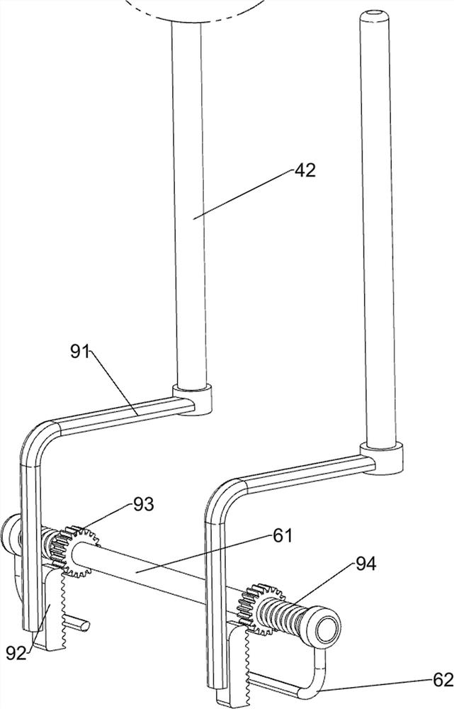
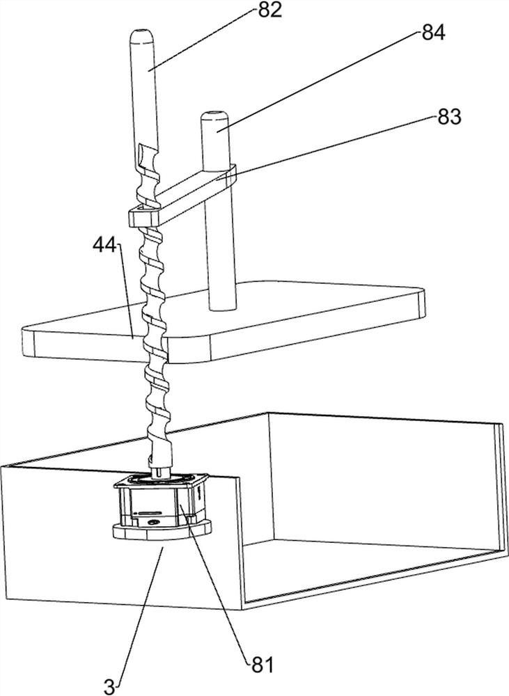
[0068] On the basis of Example 1, such as figure 2 , image 3 As shown, the pressing mechanism 4 includes a first support rod 41, a first connecting rod 42, a first spring 43, a material grinding plate 44 and a baffle plate 45, and the front and rear sides of the first discharge frame 3 are symmetrically provided with first supports. Rod 41, the inner side of the first support rod 41 on both sides is slidingly provided with the first connecting rod 42, the bottom of the two first connecting rods 42 is provided with a grinding plate 44, the lower side of the two first connecting rods 42 Both ends are wound with a first spring 43 , and both ends of the first spring 43 are respectively connected with the first connecting rod 42 and the first support rod 41 , and the left and right sides of the first discharge frame 3 are provided with baffles 45 .
[0069] When the user pushes the first connecting rod 42 to move downward by hand, the first spring 43 is driven to be stretched, a...
Embodiment 3
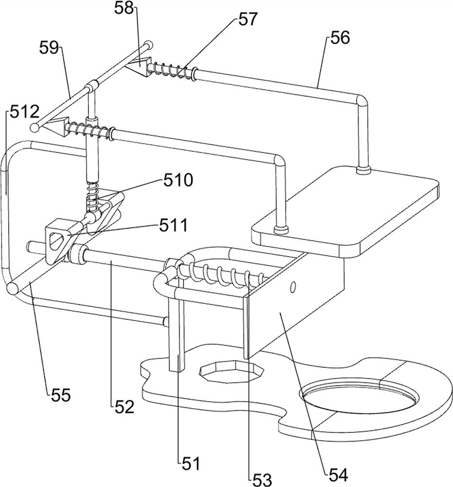
[0073] On the basis of Example 2, such as Figure 4-Figure 7 As shown, a feeding mechanism 6 is also included, and the feeding mechanism 6 includes a first rotating shaft 61, a third connecting rod 62 and a second discharging frame 63, and the right side of the second support rod 51 is symmetrically provided with a third connecting rod 62 A first rotating shaft 61 is rotatably arranged between the third connecting rods 62 on the front and rear sides, and a second discharging frame 63 is arranged in the middle of the first rotating shaft 61 .
[0074] When the pressing mechanism 4 finishes crushing the modified starch in the first discharge frame 3, the user needs to put the modified starch into the second discharge frame 63, manually turn the second discharge frame 63 to the right and pour the modified starch Enter the first discharge frame 3, manually turn the second discharge frame 63 to turn left and reset after pouring, and realize the intermittent replenishment function. ...
PUM
 Abstract
Description
Claims
Application Information
 - R&D
- Intellectual Property
- Life Sciences
- Materials
- Tech Scout
- Unparalleled Data Quality
- Higher Quality Content
- 60% Fewer Hallucinations
Browse by: Latest US Patents, China's latest patents, Technical Efficacy Thesaurus, Application Domain, Technology Topic, Popular Technical Reports.
© 2025 PatSnap. All rights reserved.Legal|Privacy policy|Modern Slavery Act Transparency Statement|Sitemap|About US| Contact US: help@patsnap.com


