Hard alloy milling cutter machining device capable of conveniently adjusting cutting depth

A technology of cutting depth and hard alloy, which is applied in metal processing equipment, metal processing machinery parts, sawing machine devices, etc., can solve the problems of scrapped milling cutters, uncontrollable depth of grooves, and easy occurrence of offset, etc., to improve cutting quality effect

Inactive Publication Date: 2021-07-09
常州肯达工具有限公司
View PDF0 Cites 2 Cited by
  • Summary
  • Abstract
  • Description
  • Claims
  • Application Information

AI Technical Summary

Problems solved by technology

[0002] A milling cutter is a rotating tool with one or more teeth for milling; each tooth cuts off the allowance of the workpiece intermittently during work. The milling cutter is mainly used for machining planes, steps, and grooves on milling machines , forming surfaces and cutting off workpieces, etc.; common materials for milling cutters are high-speed tool steel and cemented carbide, among which, the cutting speed of milling cutters made of cemented carbide is faster than that of milling cutters made of high-speed tool steel. High, and better wear resistance; in order to ensure the use of a sufficiently high average chip thickness and feed per tooth, the number of milling cutter teeth suitable for this process must be correctly determined. The milling cutter processing device is a kind of manufacturing milling cutter When tools and milling cutter processing devices open chip flutes for milling cutters, some milling cutter processing devices cannot clamp the shank of the milling cutter well during processing, so that the milling cutter is prone to deviation during processing The phenomenon affects the processing quality of the milling cutter, resulting in the scrapping of the milling cutter. The depth of the groove cannot be adjusted when slotting. For different types of milling cutters, only chip removal grooves of the same depth can be opened, which is inconvenient to use.

Method used


Image

  • Hard alloy milling cutter machining device capable of conveniently adjusting cutting depth
  • Hard alloy milling cutter machining device capable of conveniently adjusting cutting depth
  • Hard alloy milling cutter machining device capable of conveniently adjusting cutting depth

Examples


Embodiment Construction

[0029] The present invention will be further described below in conjunction with the accompanying drawings.

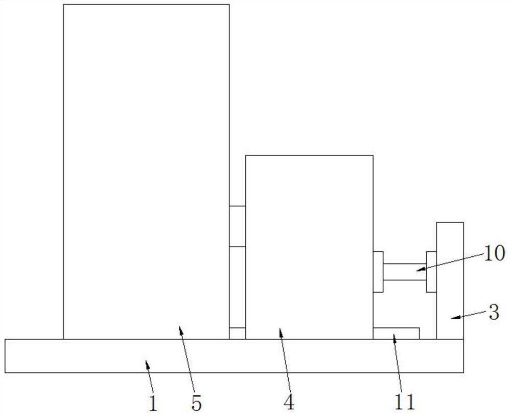
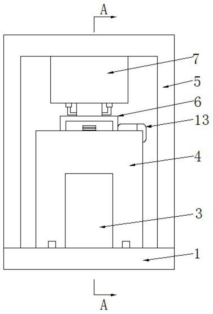
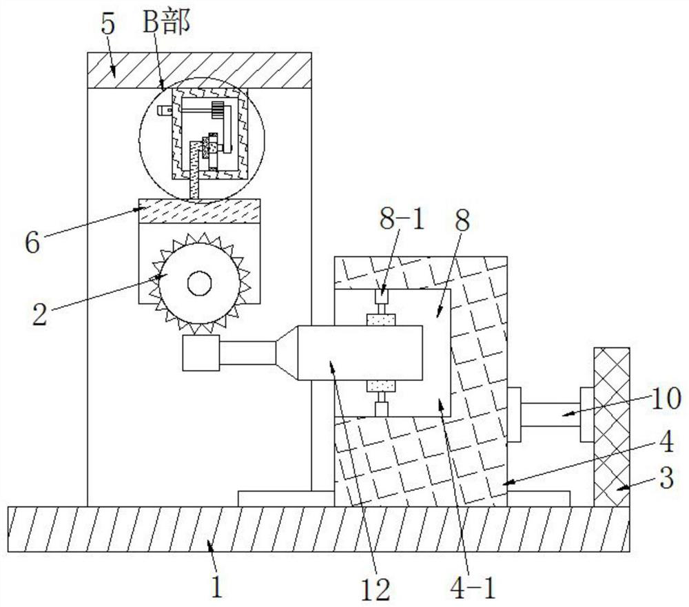
[0030] see as Figure 1-Figure 9As shown, the technical solution adopted in this specific embodiment is: it includes a working base 1 and a saw blade 2, and the working base 1 is provided with a saw blade 2; it also includes a fixed block 3, a clamping seat 4, and a support 5 , support frame 6, fixed seat 7, clamping mechanism 8 and driving mechanism 9, the upper end of the right side of the working base 1 is welded and fixed with a fixed block 3, and the left side of the fixed block 3 utilizes screws to fix the cylinder 10 of model TN20, A clamping seat 4 is welded and fixed on the pushing end of the cylinder 10, and a guide rail 11 is welded and fixed symmetrically front and rear on the working base 1. A placement slot 4-1 is provided, the knife handle in the tool 12 is set in the placement slot 4-1, and a clamping mechanism 8 is arranged between the knife handle an...


PUM


Abstract

The invention discloses a hard alloy milling cutter machining device capable of conveniently adjusting the cutting depth, and relates to the technical field of mechanical equipment. A fixed block is fixed to the upper end of the right side of a working base, an air cylinder is fixed to the left side of the fixed block, a clamping base is fixed to the pushing end of the air cylinder, a containing groove is arranged in the clamping base, a cutter handle in a cutter is arranged in the containing groove, a clamping mechanism is arranged between the cutter handle and the containing groove, a support is fixed at the upper end of the left side of the working base, a fixed seat is fixed to the bottom of the horizontal end in the support, a driving mechanism is arranged in the fixed seat, and a supporting frame is arranged on the lower side of the fixed seat. According to the hard alloy milling cutter machining device capable of conveniently adjusting the cutting depth provided by the invention, the cutter handle of a milling cutter can be clamped, the milling cutter is in a stable state during machining, the machining quality of the milling cutter is improved, the distance between a saw blade and the milling cutter is changed by driving the saw blade to be adjusted according to the machining requirement of the milling cutter, and therefore chip grooves with different depths are machined.

Description

technical field [0001] The invention relates to the technical field of mechanical equipment, in particular to a cemented carbide milling cutter processing device for conveniently adjusting the cutting depth. Background technique [0002] A milling cutter is a rotating tool with one or more teeth for milling; each tooth cuts off the allowance of the workpiece intermittently during work. The milling cutter is mainly used for machining planes, steps, and grooves on milling machines , forming surfaces and cutting off workpieces, etc.; common materials for milling cutters are high-speed tool steel and cemented carbide, among which, the cutting speed of milling cutters made of cemented carbide is faster than that of milling cutters made of high-speed tool steel. High, and better wear resistance; in order to ensure the use of a sufficiently high average chip thickness and feed per tooth, the number of milling cutter teeth suitable for this process must be correctly determined. The ...

Claims


Application Information

Patent Timeline
Patent Type & Authority Applications(China)
IPC IPC(8): B23D47/04B23D47/12B23D47/08B23Q1/25
CPCB23D47/04B23D47/042B23D47/08B23D47/12B23Q1/25
Inventor 包文峰恽克勤徐祥江禹轩巢红星
Owner 常州肯达工具有限公司
Why Eureka
Try Eureka