Spring end deburring treatment device for spring machining

A processing device and deburring technology, used in positioning devices, clamping devices, metal processing equipment, etc., can solve the problems of low work efficiency, hand injury, affecting the beauty of springs and the accuracy of installation, etc., and achieve high processing efficiency. Reduce the effect of cleanup work

Inactive Publication Date: 2021-07-09
黄淑卿
View PDF0 Cites 1 Cited by
  • Summary
  • Abstract
  • Description
  • Claims
  • Application Information

AI Technical Summary

Problems solved by technology

[0002] A spring is a mechanical part that uses elasticity to work. Parts made of elastic materials are deformed under the action of external force, and then return to their original shape after removing the external force. When the spring leaves the factory, because the surface of the spring itself is not smooth or the spring is bent The unevenness of the folding tool will cause burrs on the outer surface of the spring. The burrs not only affect the appearance of the spring and the accuracy of installation, but also cause damage to the hands of the operator during the installation process.
[0003] Most of the existing deburring methods are manually removed. This method has low work efficiency, and the removed metal shavings fall directly to the ground, making it difficult to collect and process. Therefore, a solution that can alleviate the above problems is urgently needed

Method used


Image

  • Spring end deburring treatment device for spring machining
  • Spring end deburring treatment device for spring machining
  • Spring end deburring treatment device for spring machining

Examples


Embodiment Construction

[0026] The technical solutions in the embodiments of the present invention will be clearly and completely described below in conjunction with the embodiments of the present invention. Apparently, the described embodiments are only some of the embodiments of the present invention, not all of them.

[0027] In describing the present invention, it should be understood that the terms "upper", "lower", "front", "rear", "left", "right", "top", "bottom", "inner", " The orientation or positional relationship indicated by "outside" and so on is the relative relationship of orientation or position, which is only for the convenience of describing the present invention and simplifying the description, rather than indicating or implying that the device or element referred to must have a specific orientation, or in a specific orientation. construction and operation, therefore, should not be construed as limiting the invention.

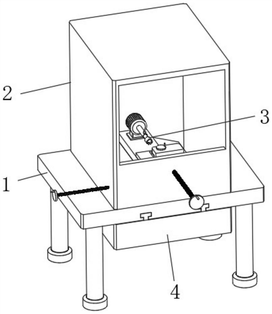
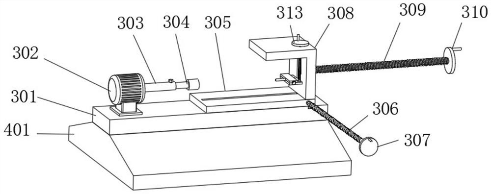
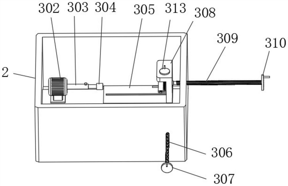
[0028] see Figure 1-8 , an embodiment provided by the presen...


PUM


Abstract

The invention discloses a spring end deburring treatment device for spring machining. The spring end deburring treatment device for spring machining comprises a base table, wherein a machining box is arranged at the upper end of the base table, a burr removing mechanism is arranged in the machining box, and the burr removing mechanism comprises a first sliding groove plate, a motor, a shaft sleeve, a cutter cylinder, a second sliding groove plate, a first screw rod, a first rotating disc, a first sliding plate, a second screw rod, a second rotating disc, a second sliding plate, a third screw rod, a third rotating disc, a hinge, a pressing plate, a limiting buckle, a telescopic column and a limiting block, and the first sliding groove plate is arranged at the position, close to the lower end, in the machining box. According to the spring end opening deburring device for spring machining, deburring treatment can be conducted on various spring end openings, the machining efficiency is high, machined metal filings can be rapidly collected, the cleaning work of the whole device is reduced, and the use requirement is better met.

Description

technical field [0001] The invention relates to the technical field of metal deburring, in particular to a spring end deburring treatment device for spring processing. Background technique [0002] A spring is a mechanical part that uses elasticity to work. Parts made of elastic materials are deformed under the action of external force, and then return to their original shape after removing the external force. When the spring leaves the factory, because the surface of the spring itself is not smooth or the spring is bent The unevenness of the folding tool will cause burrs on the outer surface of the spring. The burrs not only affect the appearance of the spring and the accuracy of installation, but also cause damage to the hands of the operator during the installation process. [0003] Most of the existing deburring methods are manually removed. This method has low work efficiency, and the removed metal shavings fall directly to the ground, making it difficult to collect and...

Claims


Application Information

Patent Timeline
Patent Type & Authority Applications(China)
IPC IPC(8): B23D79/00B23Q3/00B23Q1/25B23Q11/00
CPCB23D79/00B23Q1/25B23Q3/00B23Q11/0067B23Q2703/10
Inventor 黄淑卿
Owner 黄淑卿
Why Eureka
Try Eureka