Energy-saving bath area dehumidification barrier

A grille and bath area technology, applied in the energy application field of dehumidifiers in the bath area, can solve the problems of environmental heat pollution energy, personnel breathing difficulties, large energy consumption, etc., achieve high thermal energy quality, increase comfort, and ensure privacy Effect

Pending Publication Date: 2021-07-09
SHENYANG HONG CHENG SHIJI REFRIGERATION EQUIPCO
View PDF0 Cites 0 Cited by
  • Summary
  • Abstract
  • Description
  • Claims
  • Application Information

AI Technical Summary

Problems solved by technology

[0002] At present, in bathing places, the hot water sprayed by the shower nozzle in the bathing area will form hot and humid steam at the same time, and the mist will fill the air. On the one hand, the air humidity in the bathing area will be high and the visibility will decrease, causing difficulty in breathing and even fainting. On the other hand, This part of hot and humid steam has high temperature and high energy. The existing bath area dehumidifier method is to discharge the hot and humid air in the bath area to the outdoor environment, which not only causes environmental heat pollution and energy waste, but also forces the ambient temperature of the bath area to drop, affecting normal bathing. ; However, the existing special dehumidification equipment is not accepted by operators due to its inconvenient installation and use, high cost, high energy consumption, and poor dehumidification effect. Therefore, dehumidification in the bath area has always been an important issue for bath operators.

Method used


Image

  • Energy-saving bath area dehumidification barrier
  • Energy-saving bath area dehumidification barrier
  • Energy-saving bath area dehumidification barrier

Examples


Embodiment Construction

[0057] The present invention will be further explained below in conjunction with the accompanying drawings and embodiments.

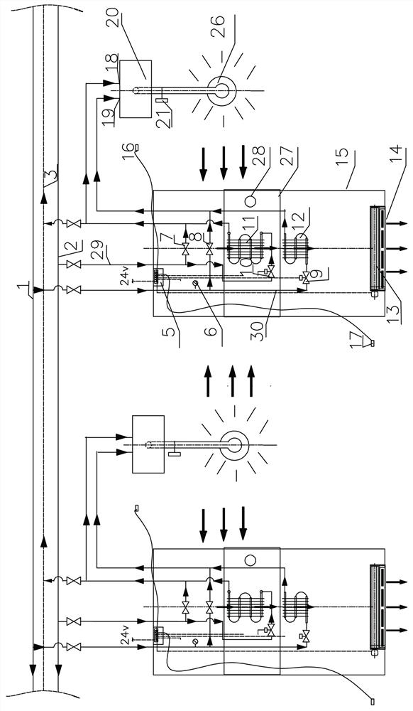
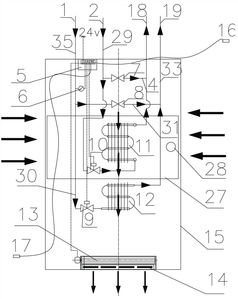
[0058] An energy-saving dehumidification grille in a bath area, comprising a fan 13 , a cold water dehumidification heat exchanger 11 and a hot water constant temperature heat exchanger 12 . The fan 13, the hot water constant temperature heat exchanger 12 and the cold water dehumidification heat exchanger 11 are all located in the casing 15 (in the front cavity 32).

[0059] The cold water inlet pipeline 29 of the cold water dehumidification heat exchanger is connected with the cold water supply main pipe 2 for the shower, and the cold water inlet pipeline 29 of the cold water dehumidification heat exchanger is provided with a cold water inlet temperature control solenoid valve 10 .

[0060] The outlet pipeline of the cold water dehumidification heat exchanger 11 is divided into two paths, one path of high-temperature fresh cold water is connected with ...


PUM


Abstract

The invention discloses an energy-saving bath area dehumidification barrier and belongs to the technical field of bath area dehumidifier energy application. A cold water inflow temperature control electromagnetic valve is arranged on a cold water inlet pipeline of a cold water dehumidification heat exchanger. An outlet pipeline of the cold water dehumidification heat exchanger is divided into two paths. A hot water inlet pipeline, a first pipeline and a hot water outlet pipeline are connected. A hot water supply pipeline water flowmeter is arranged on the hot water inlet pipeline. A box air inlet is formed in the middle of a box. The box air inlet is adjacent to the lower end of the cold water dehumidification heat exchanger. A fan is arranged at the top in the box. A box water outlet is formed in the bottom of the box. A humidity sensor is arranged outside the box. A hot water inlet pipeline of a hot water constant-temperature heat exchanger is connected between the hot water inlet pipeline and the first pipeline. A hot water inflow temperature control electromagnetic valve is arranged on the hot water inlet pipeline of the hot water constant-temperature heat exchanger. An outlet pipeline of the hot water constant-temperature heat exchanger is connected between the first pipeline and the hot water outlet pipeline. The hot water constant-temperature heat exchanger is arranged between the cold water dehumidification heat exchanger and the fan. Circulating air in a bath area is dehumidified and then heated to a constant temperature, so that the comfort is improved.

Description

technical field [0001] The invention belongs to the technical field of energy application of a bath area dehumidifier, and replaces the existing bath area dehumidification method that discharges hot and humid air in the bath area to the outdoor environment, causing heat pollution and energy waste in the outdoor environment, and forcing the ambient temperature of the bath area to decrease, thereby reducing the number of bath area dehumidifiers. Exhaust air volume and heating load, reduce energy waste, reuse waste heat energy, save energy, and improve the bathing environment. Background technique [0002] At present, in bathing places, the hot water sprayed by the shower nozzle in the bathing area will form hot and humid steam at the same time, and the mist will fill the air. On the one hand, the air humidity in the bathing area will be high and the visibility will decrease, causing difficulty in breathing and even fainting. On the other hand, This part of hot and humid steam ...

Claims


Application Information

Patent Timeline
Patent Type & Authority Applications(China)
IPC IPC(8): F24F3/14F24F11/89F24F13/00
CPCF24F3/14F24F13/00F24F2003/144F24F11/89
Inventor 高亚民王丽梅程世哲闫首弟
Owner SHENYANG HONG CHENG SHIJI REFRIGERATION EQUIPCO
Why Eureka
Try Eureka