Cylindrical microwave applicator

An applicator, cylindrical technology, used in the field of high-efficiency cylindrical microwave applicators, which can solve problems such as unevenness and poor heating

Inactive Publication Date: 2003-12-10
THE RUBBRIGHT GROUP
View PDF5 Cites 0 Cited by
  • Summary
  • Abstract
  • Description
  • Claims
  • Application Information

AI Technical Summary

Problems solved by technology

Poor or uneven heating of the underside of flat loads placed

Method used


Image

  • Cylindrical microwave applicator
  • Cylindrical microwave applicator
  • Cylindrical microwave applicator

Examples


Embodiment Construction

[0065] The present invention is a microwave applicator that efficiently and uniformly heats a load by eliminating hot and cold spots. Additionally, the present applicator uses cavity modes to eliminate edge overheating, reduce microwave energy leakage, and operate efficiently.

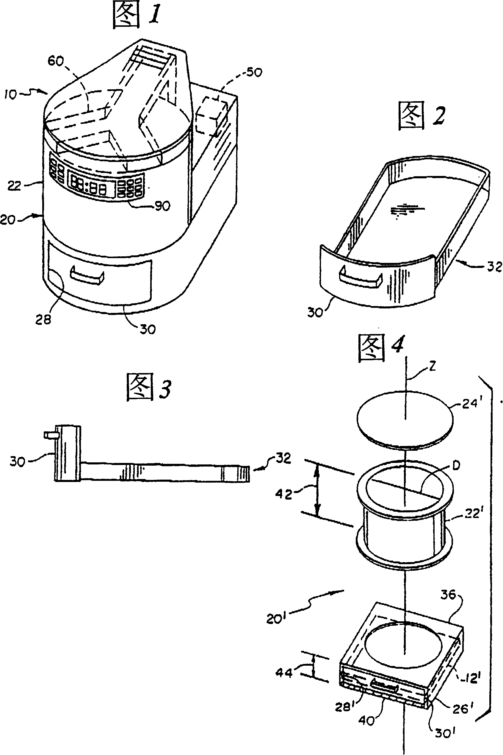
[0066] Figure 1 shows a microwave applicator 10 of the present invention. The applicator 10 includes a microwave containment chamber 20 , an energy source 50 and a feed 60 coupling the energy source 50 to the containment chamber 20 . The energy source 50 is a magnetron or other energy source capable of generating microwaves of a certain frequency, the most commonly used frequency being 2450 MHz or 915 MHz. The electronic control device 90 is for the user to control the working time of the magnetron and set the power of the magnetron. Different powers are usually set by periodically turning on / off the duty cycle of the magnetron.

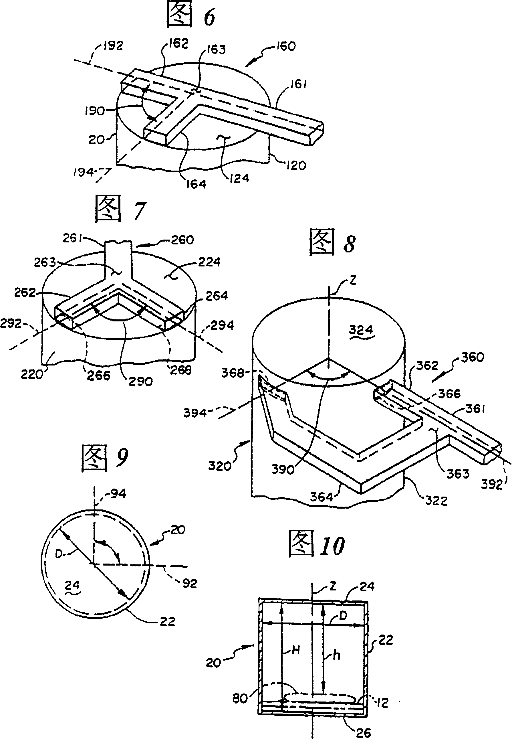
[0067] Referring to FIGS. 9 and 10 below, the microwave sealed chambe...


PUM

PropertyMeasurementUnit
The inside diameter ofaaaaaaaaaa
Heightaaaaaaaaaa

Abstract

A microwave applicator including a generally cylindrical microwave containment chamber, a microwave energy source, and a feed structure connecting the microwave energy source to the containment chamber. The diameter of the containment chamber is designed according to a process that need only take into account supporting a microwave pattern having substantially only two transverse magnetic modes, each with a characteristic guide wavelength, where the guide wavelength of one mode is substantially equal to twice the guide wavelength of the other mode. Additionally, the interior diameter can be sized to minimize the index subscript numbers of the transverse magnetic modes. The feed structure of the applicator includes at least two feed apertures spaced physically apart around the cylindrical axis of the applicator by a physical angle equal to an electrical phase shift angle of the microwaves introduced through the respective apertures, which in a preferred embodiment is 90 degrees.

Description

technical field [0001] The present invention relates to microwave applicators. More specifically, the present invention relates to a high efficiency cylindrical microwave applicator comprising a specifically sized low leakage microwave containment chamber and a feed means capable of providing a rotating electromagnetic field to heat a load without moving parts. Background technique [0002] It is well known that electromagnetic waves can transfer energy to an object or load. A microwave applicator using electromagnetic waves with a frequency of 300MHz-300GHz generally includes a microwave energy source, a microwave sealed chamber and a microwave feeding device coupling the energy source to the microwave sealed chamber. [0003] A preferred microwave energy source for the present invention is a magnetron operating at 2450 MHz, although it should be understood that since 915 MHz is the approved frequency for microwave cooking and heating, the present inv...

Claims


Application Information

Patent Timeline
IPC IPC(8): H05B6/64H05B6/70H05B6/74H05B6/80
CPCH05B6/6402H05B6/707
Inventor 佩尔·O·里斯曼查尔斯·R·比夫莱
Owner THE RUBBRIGHT GROUP
Why Eureka
Try Eureka