Automobile lampshade stamping die and stamping demolding method thereof

A stamping die and die technology, applied in the field of automobile lampshade stamping die and its stamping and demoulding, can solve the problem of easy occurrence of sticking material in the parting mold, and achieve the effects of reducing labor input, simplifying the stamping process, and being convenient to use.

Active Publication Date: 2021-07-13
苏州唯准金属制品有限公司
View PDF7 Cites 3 Cited by
  • Summary
  • Abstract
  • Description
  • Claims
  • Application Information

AI Technical Summary

Problems solved by technology

[0003] However, this stamping die is prone to sticking when parting the mold, so it is necessary to design a stamping die for automobile lampshades that can be automatically demolded

Method used


Image

  • Automobile lampshade stamping die and stamping demolding method thereof
  • Automobile lampshade stamping die and stamping demolding method thereof
  • Automobile lampshade stamping die and stamping demolding method thereof

Examples


Embodiment 1

[0035] In this embodiment, the workpiece is a sheet material used for an automobile lampshade, and the workpiece is punched through the stamping die to remove waste materials in the middle of the workpiece.

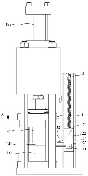
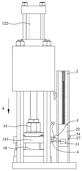
[0036] A direction is the moving direction of the upper template 14, and B direction is the moving direction of the workpiece.

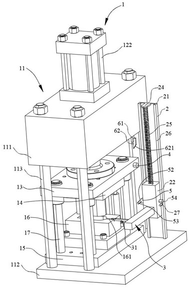
[0037] as shown in Figure 1 to Figure 9 As shown, the present embodiment provides a stamping die for an automobile lampshade, comprising:

[0038] mold body 1,

[0039] The mold body 1 includes an outer frame 11, which is composed of two top plates 111 and a bottom plate 112 arranged parallel to each other, and the top plate 111 and the bottom plate 112 are fixed by four fixing columns 113 at four corners. The top of the outer frame 11 is fixed with a drive cylinder 122. Specifically, the fixed end of the drive cylinder 122 is fixed on the top of the top plate 111, and the drive cylinder 122 is set upside down. The movable end of the drive cyli...

Embodiment 2

[0058] On the basis of Embodiment 1, this Embodiment 2 also provides a stamping and demoulding method for stamping dies for automobile lampshades, wherein a stamping die for automobile lampshades is the same as Embodiment 1, and will not be repeated here. In the gap 33, insert the locking block 321 into the locking groove 311, and when a "click" is heard, the upper plate 32 is clamped to clamp the workpiece; the upper mold base 13 is driven by the driving cylinder 122 to drive the upper template 14 and the lower template 16 Close the mold to stamp the workpiece; push the linkage surface 52 through the push rod 4 to drive the connecting rod 5 to compress the telescopic spring 51, so that the push rod 4 crosses the connecting rod 5 downward; drive the upper mold base 13 through the driving cylinder 122 to drive the upper template 14 and The lower template 16 is divided into molds, the push rod 4 drives the slider 22 to lift upward along the longitudinal guide rail 2 through the l...


PUM


Abstract

The invention relates to the technical field of automobile accessories, in particular to an automobile lampshade stamping die and a stamping and demolding method thereof. The automobile lampshade stamping die comprises a die body and a clamping mechanism; a push rod is fixedly connected to the movable part of the die body; when an upper die plate and a lower die plate are split, the push rod can be linked with the clamping mechanism to drive a workpiece to lift, so that the workpiece and the lower die plate are demolded; after the workpiece is lifted to a certain height, the push rod can loosen the clamping mechanism, a sliding block slides downwards along a longitudinal guide rail under the action of gravity so that the workpiece and the upper die plate can be demolded, then the workpiece can be demolded automatically, the situation that materials adhere to the workpiece after stamping is completed is avoided, and potential safety hazards caused by manual demolding are reduced; and after the workpiece is demoulded, the workpiece slides downwards and impacts the lower die plate to shake off waste materials on the workpiece, the lower die plate further plays a role in removing the waste materials on the workpiece, use is convenient and fast, the waste materials do not need to be removed manually, the stamping procedure is simplified, and manpower input is reduced.

Description

technical field [0001] The invention relates to the technical field of auto parts processing, in particular to a stamping die for an automobile lampshade and a stamping and demoulding method thereof. Background technique [0002] Chinese patent, the application number is CN202021384704.0, the application date is 2020.07.14, the publication number is CN212945018U, and the authorization announcement date is 2021.04.13. It provides a new type of automobile lampshade precision stamping die, including a stamping die, and the upper end of the stamping die is fixed The connecting part connected with the driving device is installed, the stamping part is fixedly installed in the middle of the stamping die, the bottom of the stamping die is fixedly provided with a mold base, and the upper end surface of the mold base is movably installed with a mold liner, and the upper end of the mold liner is also set There is a mold cover, the outer wall of the mold liner is movably connected with ...

Claims


Application Information

Patent Timeline
Patent Type & Authority Applications(China)
IPC IPC(8): B21D37/10B21D45/04B21D22/02B08B7/02B21D43/00B21D53/88
CPCB08B7/02B21D22/02B21D37/10B21D43/003B21D45/04B21D53/88
Inventor 沈煜黄璐
Owner 苏州唯准金属制品有限公司
Why Eureka
Try Eureka