Wake-up signal generating circuit and vehicle charging system
A technology for waking up signals and generating circuits, applied in electric vehicle charging technology, charging stations, electric vehicles, etc., can solve problems such as the inability to wake up the controller, the inability to fully realize the expected output signal scheme, and the inability of the controller to enter sleep, etc.
- Summary
- Abstract
- Description
- Claims
- Application Information
AI Technical Summary
Problems solved by technology
Method used
Image

Examples
Embodiment 1
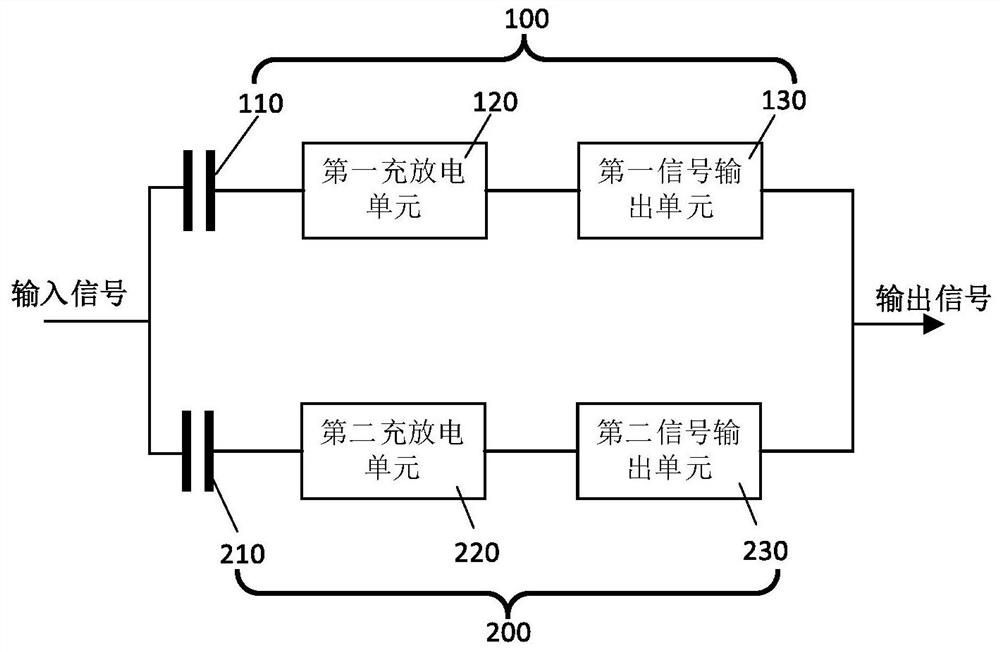
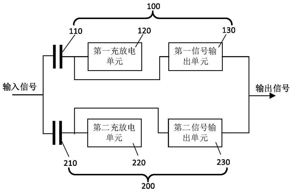
[0063] Please refer to Figure 2a and Figure 2b ,in, Figure 2a It is a schematic structural diagram of a wake-up signal generating circuit according to an embodiment of the present invention; Figure 2b It is a structural schematic diagram of a wake-up signal generating circuit according to another embodiment of the present invention.
[0064] The wake-up signal generating circuit of this embodiment is as Figure 2a shown. The signal trigger circuit includes a first trigger module 100 and a second trigger module 200, the input of the first trigger module 100 is connected to the input of the second trigger module 200, and the output of the first trigger module 100 terminal is connected to the output terminal of the second trigger module 200; in this embodiment, the input terminal of the first trigger module 100 is configured as the input terminal of the signal trigger circuit, and the input terminal of the first trigger module 100 The output terminal is configured as the...
Embodiment 2
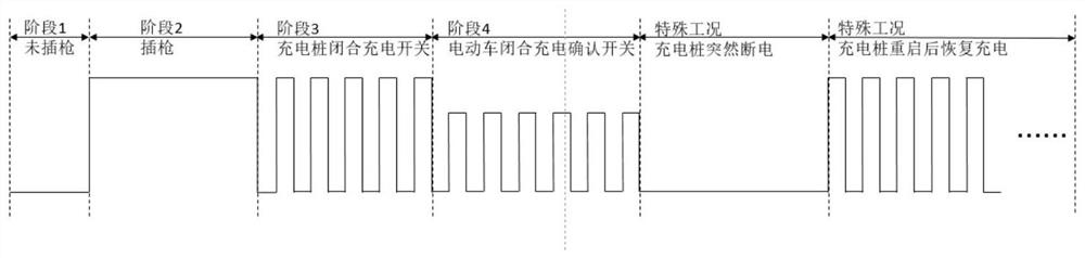
[0099] Please refer to Figure 3 to Figure 6 ,in, image 3 It is a schematic circuit diagram of a wake-up signal generating circuit according to an embodiment of the present invention; Figure 4 It is a schematic diagram of the waveforms of the wake-up signal generating circuit in an embodiment of the present invention when the gun is not inserted, the instant when the gun is switched to the inserted gun, and the gun is inserted and the charging switch is not closed; Figure 5 It is a schematic diagram of the waveforms of the wake-up signal generating circuit of an embodiment of the present invention at the moment when the gun is inserted and the charging switch is not closed, at the moment when the gun is inserted and the charging switch is closed, and after the gun is inserted and the charging switch is closed; Figure 6 It is a schematic diagram of the waveforms of the wake-up signal generating circuit in an embodiment of the present invention after the charging pile is po...
Embodiment 3
[0140] This embodiment provides a vehicle charging system, including a vehicle charging port, the above-mentioned wake-up signal generating circuit and a controller;
[0141] The controller includes a wake-up signal input terminal, and the controller is used to receive the first level through the wake-up signal input terminal and switch its own state to a working mode;
[0142] The input end of the first trigger module is connected to the charging port of the vehicle, and the output end of the first trigger module is connected to the wake-up signal input end.
[0143] Since the above-mentioned wake-up signal generation circuit is adopted in this embodiment, the controller can be woken up at an appropriate time to perform necessary logic control, and sleep at other times to reduce energy consumption, which has a better effect.
[0144] To sum up, in the wake-up signal generating circuit and the vehicle charging system provided by Embodiments 1 to 3, the signal triggering circui...
PUM
 Abstract
Description
Claims
Application Information
 - R&D
- Intellectual Property
- Life Sciences
- Materials
- Tech Scout
- Unparalleled Data Quality
- Higher Quality Content
- 60% Fewer Hallucinations
Browse by: Latest US Patents, China's latest patents, Technical Efficacy Thesaurus, Application Domain, Technology Topic, Popular Technical Reports.
© 2025 PatSnap. All rights reserved.Legal|Privacy policy|Modern Slavery Act Transparency Statement|Sitemap|About US| Contact US: help@patsnap.com