
Vacuum film transfer suction cup device

A suction cup and film technology, which is applied in the directions of transportation and packaging, removing smoke and dust, and sending objects, can solve the problems of unsmooth paper feeding, uneven paper feeding speed, and poor position accuracy, so as to achieve convenient paper picking and improve Convenience, easy disassembly effect

Inactive Publication Date: 2021-07-13
江苏璇枢医疗科技有限公司
View PDF9 Cites 2 Cited by
  • Summary
  • Abstract
  • Description
  • Claims
  • Application Information

AI Technical Summary

Problems solved by technology

[0004] Aiming at the deficiencies of the prior art, the present invention provides a vacuum film transfer sucker device, which solves the problem that in the existing film printing mentioned in the above-mentioned background technology, the film feeding device is mostly in the form of rubbing paper, which is easy to produce the following disadvantages, multiple sheets sticking together , one sheet brings out multiple sheets, paper feeding is not smooth, multi-site transfer is not in place, paper feeding speed is uneven, position accuracy is poor, and the existing paper picking mechanism is mainly a roller device, which requires more expensive costs and is relatively expensive. Complex institutions also require a larger space

Method used

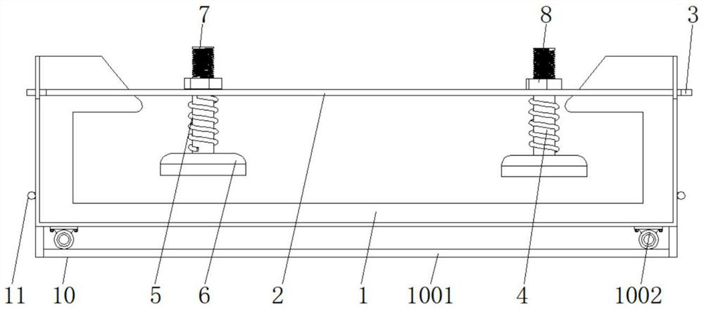
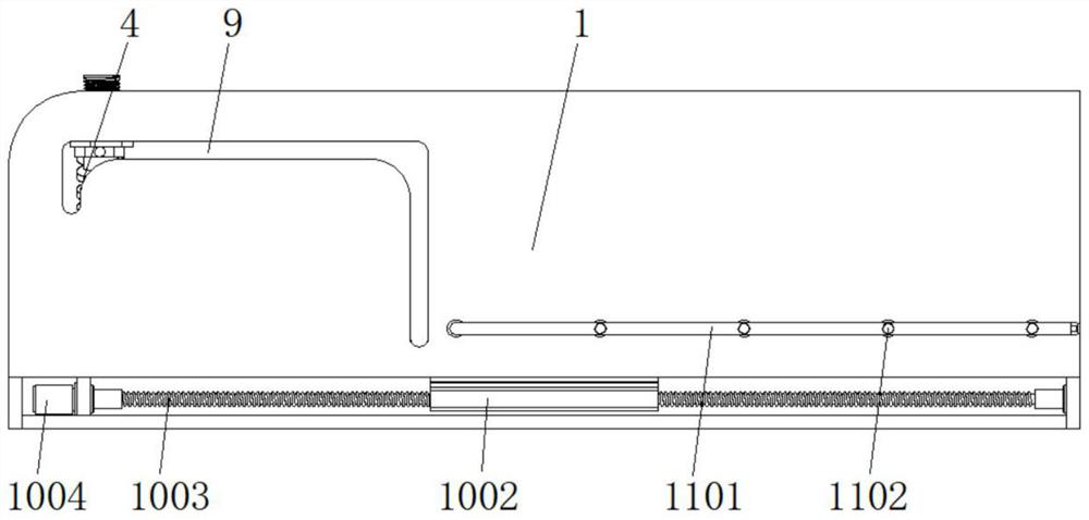
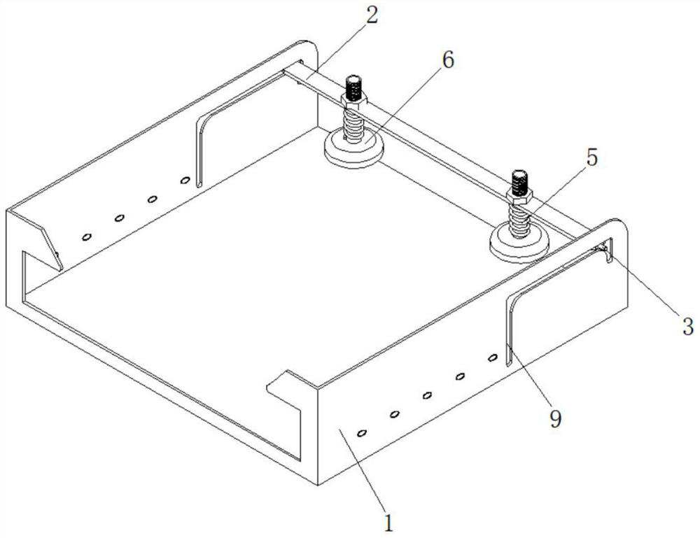

Image

  • Vacuum film transfer suction cup device
  • Vacuum film transfer suction cup device
  • Vacuum film transfer suction cup device

Examples


Embodiment Construction

[0025] The following will clearly and completely describe the technical solutions in the embodiments of the present invention with reference to the accompanying drawings in the embodiments of the present invention. Obviously, the described embodiments are only some, not all, embodiments of the present invention.

[0026] In the description of the present invention, unless otherwise stated, the meaning of "plurality" is two or more; the terms "upper", "lower", "left", "right", "inner", "outer" , "front end", "rear end", "head", "tail", etc. indicate the orientation or positional relationship based on the orientation or positional relationship shown in the drawings, and are only for the convenience of describing the present invention and simplifying the description, rather than Nothing indicating or implying that a referenced device or element must have a particular orientation, be constructed, and operate in a particular orientation should therefore not be construed as limiting ...


PUM


Abstract

The invention discloses a vacuum film transfer suction cup device, and relates to the field of vacuum film transfer suction cups, in particular to the vacuum film transfer suction cup device which comprises a transfer bin body, an auxiliary positioning disassembly and assembly mechanism and a dust removal mechanism. A cavity is formed in the transfer bin body, a transverse plate is arranged in the cavity, and cylinders are connected to the tail ends of the two ends of the transverse plate. Shaft columns are connected to the left side and the right side of the transverse plate in a penetrating mode, return springs arranged outside the shaft columns in a sleeving mode, positioning nuts are fixedly connected to the tops of the shaft columns, and suction cups are connected to the bottoms of the shaft columns. Notches are formed in the two sides of the inner wall of the transfer bin body, and the auxiliary positioning disassembly and assembly mechanism is located below the transfer bin body. The notches formed in the vacuum film transfer suction cup device control the movement of the cylinders and further control the suction cups, when the cylinders are located at the front ends of the inner walls of the notches, the suction cups press paper to generate adsorption force, and the cylinders move along the interiors of the notches until the cylinders move to the rear ends of the inner walls of the notches, so that the suction cups move the paper.

Description

technical field [0001] The invention relates to the technical field of vacuum film transfer suction cups, in particular to a vacuum film transfer suction cup device. Background technique [0002] Existing image processing devices (thermal film printers) usually have a paper tray, in which multiple sheets of film printing media to be output are placed. If it is desired to send the paper in the paper feeding tray to the printing body of the image processing device for printing one by one, it is necessary to feed the paper into the printing body through another paper-feeding and paper-feeding mechanism. In the existing film printing, the film feeding device is mostly in the form of rubbing paper, which is prone to the following disadvantages: multiple sheets stick together, one sheet carries out multiple sheets, paper feeding is not smooth, multi-site transfer is not in place, and paper feeding speed is uneven. Location accuracy is poor. [0003] The existing paper fetching m...

Claims


Application Information

Patent Timeline
Patent Type & Authority Applications(China)
IPC IPC(8): B65H29/24B08B5/04B08B15/04
CPCB65H29/241B08B5/04B08B15/04B65H2701/10B65H2801/03
Inventor 巢渊芦俊曹璇杨红义
Owner 江苏璇枢医疗科技有限公司
Learn More