Lifting equipment based on different-direction non-equidistant double-barrel spiral driving structure
A lifting equipment, screw drive technology, applied in elevators, stepped structures, lifting devices, etc., can solve the problems of multi-material, high cost, etc.
- Summary
- Abstract
- Description
- Claims
- Application Information
AI Technical Summary
Problems solved by technology
Method used
Image
Examples
Embodiment 1
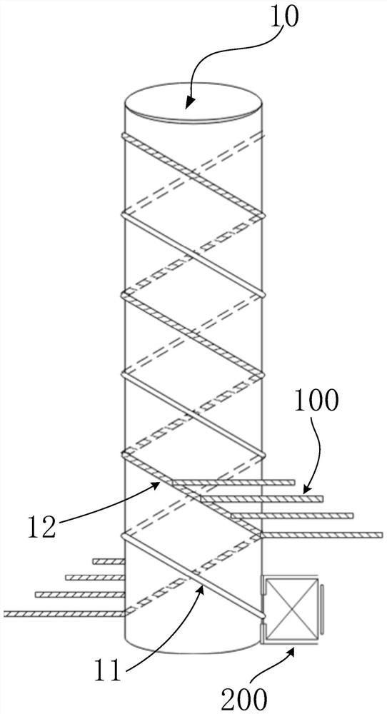
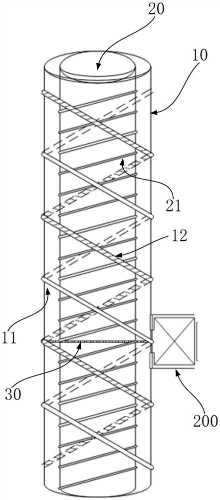
[0032] The invention provides an elevator / lifting device, which can cooperate with a revolving staircase to realize the separation of the elevator passage and the stair passage in a stair passage. In different ways, the transmission structure can be simplified and the load on the elevator and / or lifting equipment can be optimized in a limited space, so that the elevator / lifting equipment can run safely and stably. It should be noted that existing buildings without elevators / lifting devices are usually rebuilt based on the pedestrian passage walls in the stairwell to install elevators, and there are the following problems:
[0033] 1. The existing traction and hydraulic transmissions have the problems of unstable operation, large renovation space and large functional requirements;
[0034] 2. The modification method of hanging the elevator along the pedestrian passage wall in the stairwell. The elevator car or the bearing mechanism is equivalent to a cantilever beam, which only t...
Embodiment 2
[0049] This embodiment is a further improvement and / or supplement to Embodiment 1, and repeated content will not be repeated here.
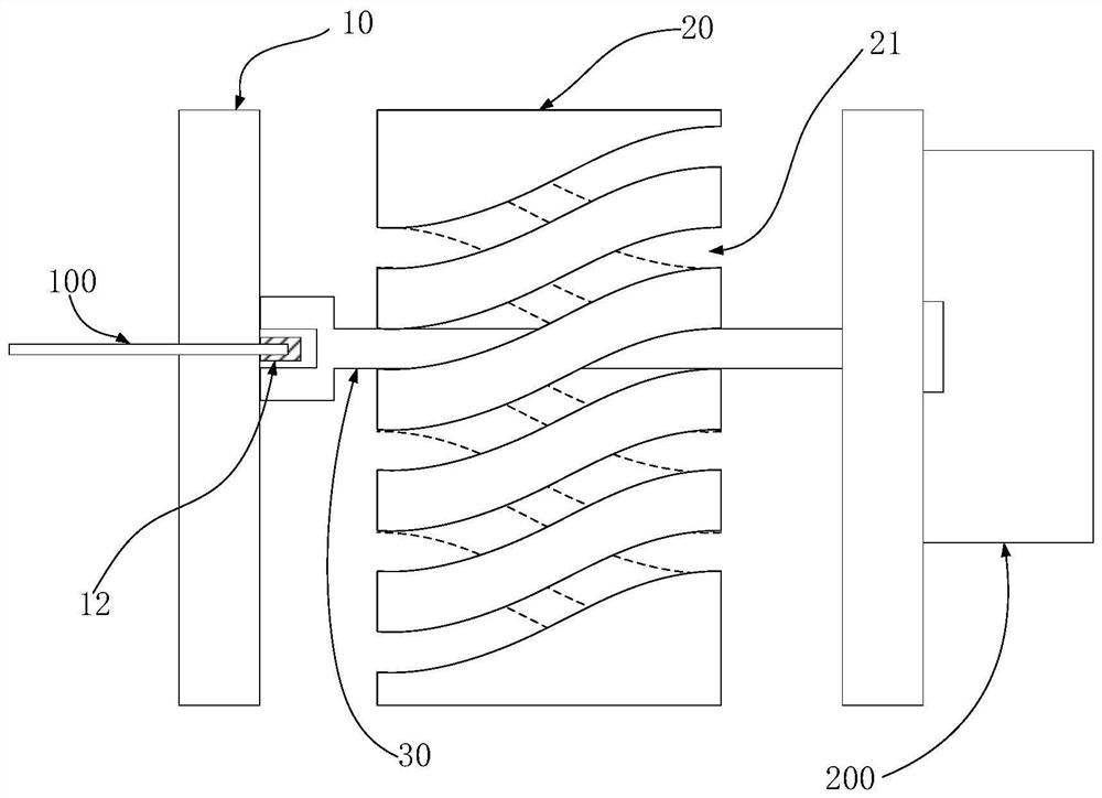
[0050] see figure 2 In Embodiment 1, the connecting body 30 is a simply supported beam structure with respect to the first supporting body 20. One side of the connecting body 30 abuts against the first supporting body 10 through the first groove body 11, and the other side passes through the first convex body 12. To abut against the first support body 10 , this embodiment describes the way of connection and / or abutment between the connecting body 30 and the first convex body 12 .
[0051] see image 3 and Figure 4 , the first support body 10 is provided with a first convex body 12 opposite to the first carrier body 100 . Preferably, the first carrier 100 passes through a side wall of one side of the first support 10 . The end of the first carrier 100 can be inserted into the first convex body 12 . One side of the first protrusion 12 is in ...
Embodiment 3
[0061] This embodiment is a further improvement and / or supplement to Embodiments 1 and 2 and their combination, and the repeated content will not be repeated.
[0062] In Embodiment 1 and Embodiment 2, there may be problems of slippage and wear in the abutment and / or connection between the connecting body 30 and the second groove body 21. This embodiment aims at the connection and / against the way to improve.
[0063] Preferably, the connecting body 30 can move along the first groove body 11 . The connecting body 30 can move along the second groove body 21 . Preferably, the second tank body 21 / the first tank body 11 and the connecting body 30 move relative to each other. The connecting body 30 can relatively slide / roll along the first groove body 11 and / or the second groove body 21 .
[0064] Preferably, the connecting body 30 can also be connected with the second tank body 21 . The connecting body 30 can also be connected with the first tank body 11 . In this implement...
PUM
 Abstract
Description
Claims
Application Information
 - R&D
- Intellectual Property
- Life Sciences
- Materials
- Tech Scout
- Unparalleled Data Quality
- Higher Quality Content
- 60% Fewer Hallucinations
Browse by: Latest US Patents, China's latest patents, Technical Efficacy Thesaurus, Application Domain, Technology Topic, Popular Technical Reports.
© 2025 PatSnap. All rights reserved.Legal|Privacy policy|Modern Slavery Act Transparency Statement|Sitemap|About US| Contact US: help@patsnap.com


