
Drip-proof filling needle for filling machine

A filling machine and anti-drip technology, applied in the field of machinery and equipment, can solve the problems of difficult gas, increase production costs, affect the normality of equipment, etc., and achieve the effects of low production cost, production cost saving, and production cleaning cost saving.

Pending Publication Date: 2021-07-13
连云港宝畅流体输送设备有限公司
View PDF0 Cites 0 Cited by
  • Summary
  • Abstract
  • Description
  • Claims
  • Application Information

AI Technical Summary

Problems solved by technology

Therefore, at present, the filling machine has been widely used in the automatic filling production of pharmaceutical, daily chemical, food and special industry factories. The filling machine uses the principle of pressure filling, and the filling needs to be completed as soon as possible in a short time. When the pressure is high, more air bubbles will be generated, and the gas in the filling bottle is not easy, and the sealing performance of the existing filling needle in the filling process mainly depends on the sealing rubber strip, and the product will affect the sealing rubber strip. The prolongation of the use time makes it difficult to guarantee the sealing performance, and dripping will occur in the actual use process. On the one hand, the dripping liquid needs to be cleaned up, which seriously affects the normal operation of the equipment. On the other hand, too much solution is wasted, which increases the production cost. We need a drip-proof filling needle for filling machine

Method used


Image

  • Drip-proof filling needle for filling machine
  • Drip-proof filling needle for filling machine
  • Drip-proof filling needle for filling machine

Examples


Embodiment 1

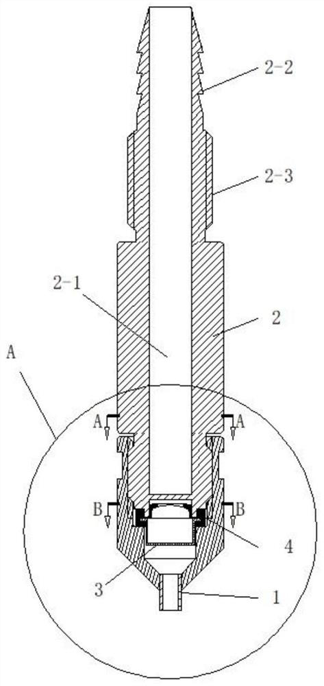
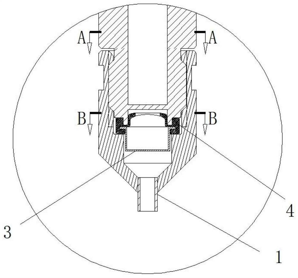
[0021] see Figure 1-Figure 5 , the present invention provides a technical solution:

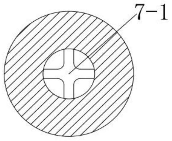
[0022] An anti-drip filling needle for a filling machine, characterized in that it includes a syringe 2 and a needle 1, the syringe 2 and the needle 1 are connected to form a whole, and the syringe 2 is provided with a filling chamber 2-1, the connection between the syringe 2 and the needle 1 is provided with a silicone valve 4, the top of the silicone valve 4 is provided with a cross-shaped opening 4-1, and the lower part of the filling chamber 2-1 There is a discharge port 2-1-1, the upper part of the syringe is provided with a pipe joint 2-2, the lower part of the pipe joint 2-2 is provided with a fixed thread 2-3, and the fixed thread 2-3 is used to connect with the filling Installed and fixedly connected, the shape of the discharge port 2-1-1 is a "cross" structure, and the discharge port 2-1-1 is connected to the cross-shaped opening 4-1 on the silica gel valve 4. Corresponding to th...


PUM


Abstract

The invention discloses a drip-proof filling needle for a filling machine, and belongs to the technical field of filling equipment. The drip-proof filling needle comprises a needle cylinder and a needle head, wherein the needle cylinder and the needle head are connected into a whole, the needle cylinder and the needle head are connected together, a filling cavity is arranged in the needle cylinder, a silica gel valve is arranged at the joint of the needle cylinder and the needle head, and a cross-shaped opening is formed in the top of the silica gel valve. After filling is completed, the cross-shaped opening of the silica gel valve deforms and returns to the original state to form sealing, a discharging port is formed in the lower portion of the filling cavity, a pipe connector is arranged on the upper portion of the needle cylinder and used for being connected with a feeding pipe for feeding, and a fixing thread is arranged on the lower portion of the pipe connector and used for being fixedly connected with the filling machine. In order to improve the sealing communication effect, the discharging port is in a cross shape, and the discharging port is correspondingly communicated with the cross-shaped opening in the silica gel valve. The technical problems that existing equipment needs to be cleaned and filling liquid is wasted in the production process are solved, and the filling liquid filling device is mainly applied to the filling machine for filling liquid filling.

Description

technical field [0001] The invention belongs to the technical field of mechanical equipment, in particular to an anti-drip filling needle for a filling machine. Background technique [0002] The filling machine is widely used in production enterprises. The filling machine is a kind of filling material used to fill various filling materials such as gas-containing liquid, non-gas liquid and paste into bottles, cans, boxes, barrels or bags, etc. For the mechanical equipment in the packaging container, the use of mechanized filling can not only improve productivity, reduce product loss, ensure packaging quality, but also reduce mutual pollution between the production environment and the loaded materials. Therefore, at present, the filling machine has been widely used in the automatic filling production of pharmaceutical, daily chemical, food and special industry factories. The filling machine uses the principle of pressure filling, and the filling needs to be completed as soon a...

Claims


Application Information

Patent Timeline
Patent Type & Authority Applications(China)
IPC IPC(8): B67C3/28B67C3/26B67C3/22
CPCB67C3/28B67C3/26B67C3/22
Inventor 韩少川孟伟伟张涛许任
Owner 连云港宝畅流体输送设备有限公司
Learn More