Intelligent movable cleaning device
A mobile cleaning device and intelligent technology, which can be applied to road surface cleaning, cleaning methods, animal houses, etc., can solve the problems of high labor intensity, large investment of manpower and material resources, time-consuming and labor-intensive problems, etc.
- Summary
- Abstract
- Description
- Claims
- Application Information
AI Technical Summary
Problems solved by technology
Method used
Image
Examples
Embodiment 1
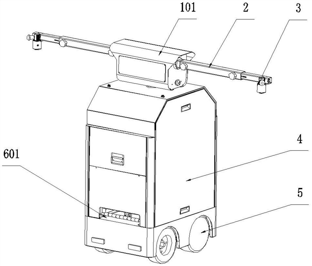
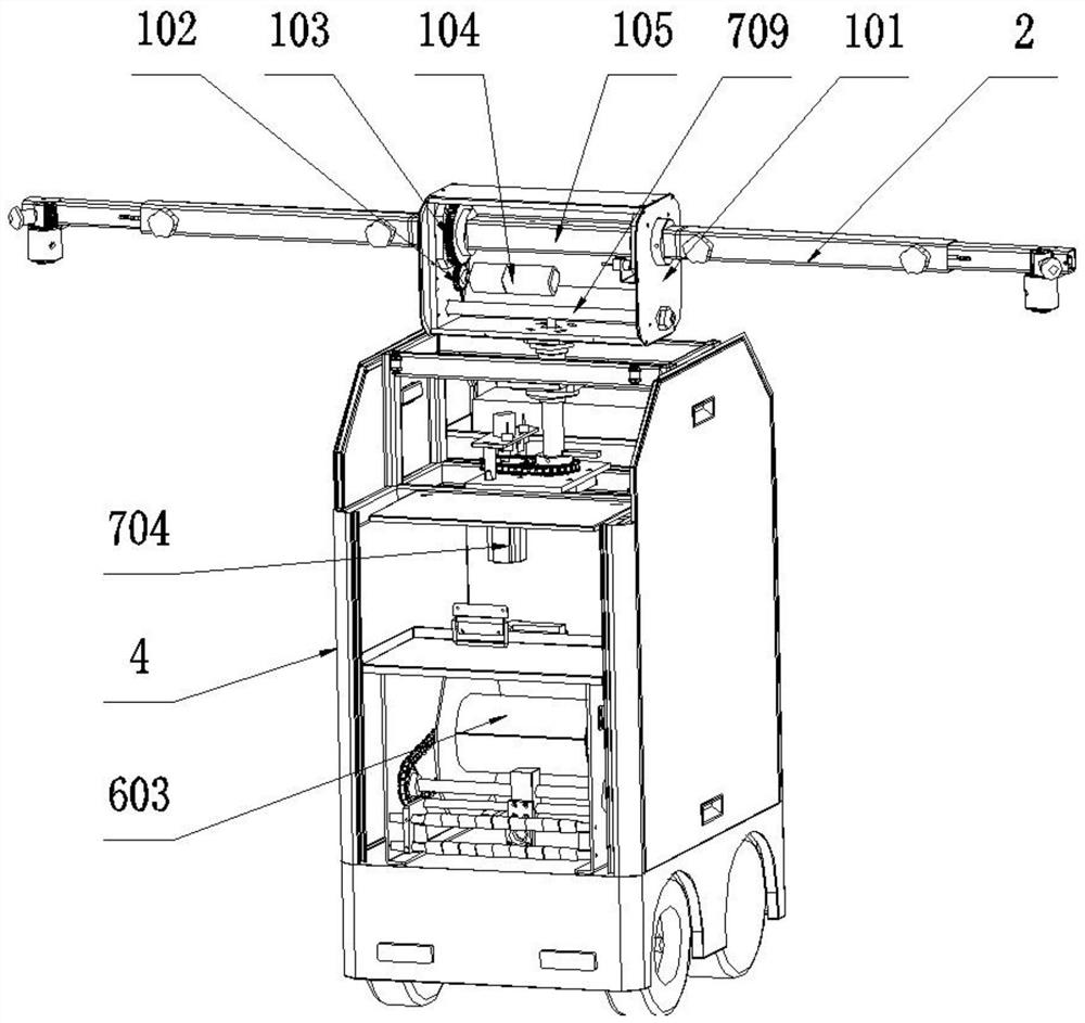
[0024] Such as figure 1 and figure 2 As shown, an intelligent mobile cleaning device includes a body 4, a moving mechanism 5 and a pipe outlet 601. The bottom of the body 4 is provided with a moving mechanism 5, which drives the body 4 to automatically move through the moving mechanism 5. The moving mechanism 5 is a prior art. Any mechanism that can move automatically in the prior art can be used, and rollers can also be installed at the bottom of the body 4 to realize the purpose of moving by pushing the body 4 to move. The body 4 is provided with a pipe outlet 601, and the water pipe can pass through the pipe outlet 601 to be wound on the pipe coiling mechanism. The pipe coiling mechanism is provided in the body 4 to avoid the water pipes from being entangled during the movement of the device, thereby affecting the normal water flow. Excessive water pressure from the flow can cause the pipe to burst or damage the unit. The body 4 is provided with a coiling mechanism on wh...
Embodiment 2
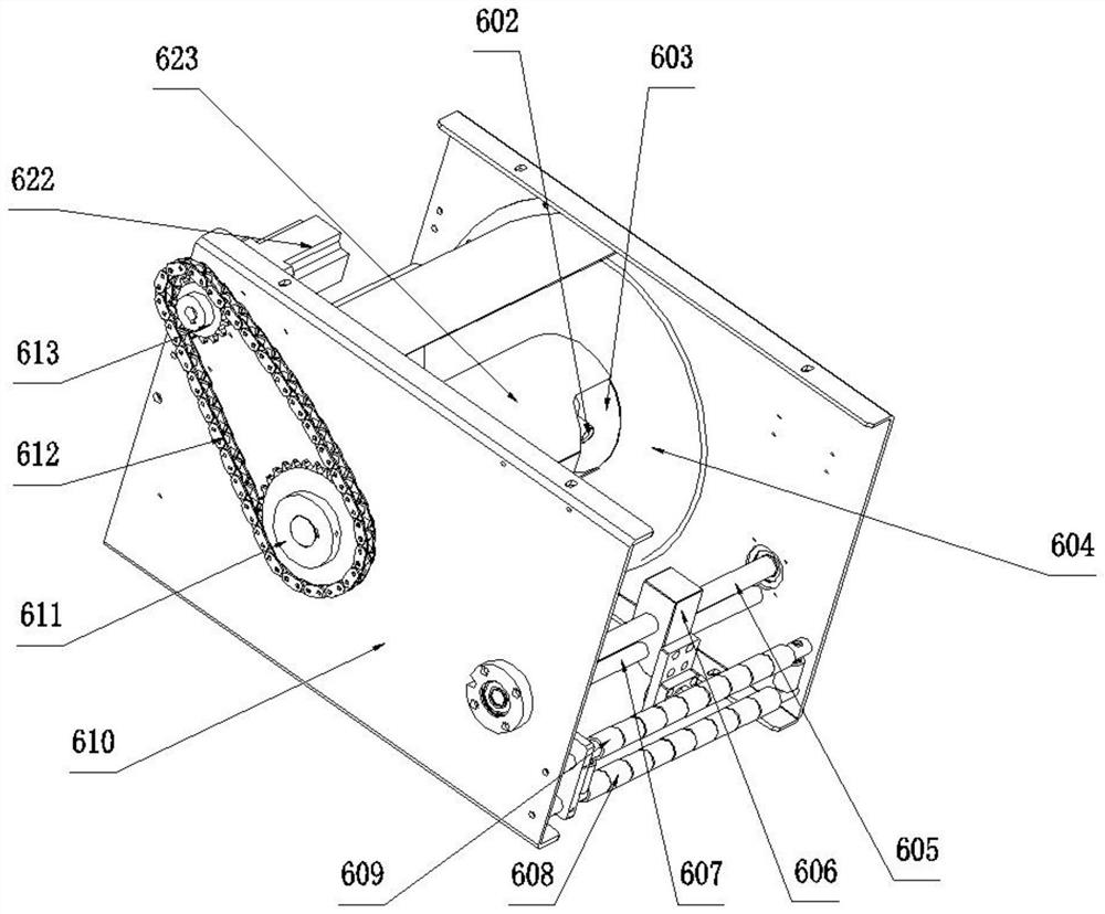
[0027] see image 3 and Figure 4 As mentioned above, this embodiment is the same as the other structures of Embodiment 1, the difference is that the coiling mechanism adopts the following mechanism, and the coiling mechanism includes a mounting frame 610, a driving mechanism, a winding mechanism and a water pipe guiding mechanism, and the mounting frame 610 is provided with a driving mechanism, the driving mechanism is connected with the winding mechanism, the winding mechanism is connected with the installation frame 610 through bearing rotation, the installation frame 610 is provided with a water pipe guiding mechanism, and the water pipe guiding mechanism is located between the winding mechanism and the outlet 601 Between, the water pipe guide mechanism is connected with the pipe winding mechanism. The driving mechanism in the coiling mechanism drives the winding mechanism to rotate so that the water pipe can be wound on the winding mechanism or the pipe is released. When...
Embodiment 3
[0036] see Figure 5 , the other structure of this embodiment is the same as that of Embodiment 1, the difference is that the rotating mechanism is different, specifically as follows:
[0037] Described rotating mechanism comprises rotating motor 704, rotating sprocket A703, rotating chain 705, rotating sprocket B706, rotating bar 709 and rotating shaft 708, described rotating motor 704 is connected with rotating sprocket A703, rotating sprocket A703 and rotating One end of the chain 705 is engaged, the other end of the rotating chain 705 is engaged with the rotating sprocket B706, the output end of the rotating sprocket B706 is connected with one end of the rotating shaft 708, and the other end of the rotating shaft 708 passes through the top wall of the body 4 and the rotating rod 709 Connected, the rotating rod 709 is located in the rotating box 101. The rotating box 101 is driven to rotate by the rotating mechanism.
[0038] The output end of the rotating sprocket A703 i...
PUM
 Abstract
Description
Claims
Application Information
 - R&D
- Intellectual Property
- Life Sciences
- Materials
- Tech Scout
- Unparalleled Data Quality
- Higher Quality Content
- 60% Fewer Hallucinations
Browse by: Latest US Patents, China's latest patents, Technical Efficacy Thesaurus, Application Domain, Technology Topic, Popular Technical Reports.
© 2025 PatSnap. All rights reserved.Legal|Privacy policy|Modern Slavery Act Transparency Statement|Sitemap|About US| Contact US: help@patsnap.com


