
Downhole injection allocation device for oil field producing well

A technology for oil production wells and injectors, which is applied in the direction of wellbore/well components, wellbore/well valve devices, production fluids, etc. It can solve the problems of high cost, large amount of cable usage, and low success rate of fishing. Achieve the effect of reducing operating costs, simplifying operating procedures, and reducing operating risks

Active Publication Date: 2021-07-13
DAQING SHENGWEI MACHINERY MFG
View PDF5 Cites 0 Cited by
  • Summary
  • Abstract
  • Description
  • Claims
  • Application Information

AI Technical Summary

Problems solved by technology

After the traditional dispenser is installed, it is necessary to take out the plug in the dispenser through downhole operation, and adjust the injection volume by replacing the water nozzle in the plug. This adjustment method often occurs during implementation. The thrower is stuck, and the success rate of throwing is low, which seriously affects the operation efficiency
For this reason, the electric dispenser came into being. The working principle of the electric dispenser is to open or close the dispensing channel by driving the plug to rotate through the motor. Downhole, which brings risks to the operation, and the use of cables is large and the cost is high

Method used


Image

  • Downhole injection allocation device for oil field producing well
  • Downhole injection allocation device for oil field producing well
  • Downhole injection allocation device for oil field producing well

Examples


Embodiment Construction

[0033] In order to make the technical problems, technical solutions and beneficial effects to be solved by the present invention clearer, the present invention will be further described in detail below in conjunction with the accompanying drawings and embodiments.

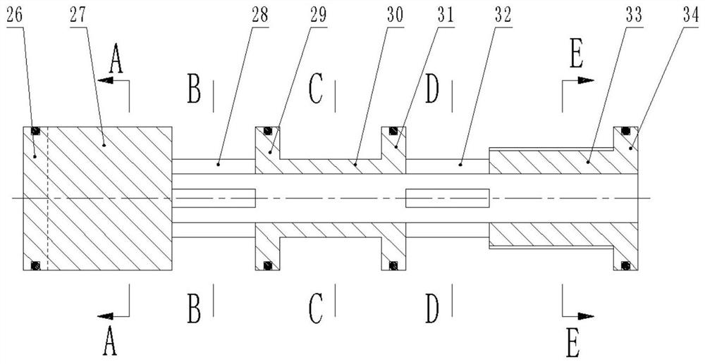
[0034]The present invention comprises upper joint 1, upper jacket 23, upper central pipe 5, valve core seat 7, lower outer coat 16, lower central pipe 15, lower joint 17 and spool, upper joint 1, upper outer coat 23, valve core seat 7 and The upper central pipe 23 encloses an upper chamber, the lower joint 17, the lower outer jacket 16, the valve core seat 7 and the lower central pipe 15 enclose a lower chamber, and the valve core is installed on one of the valve core bases 7 In the axial hole, a liquid inlet hole 10 and a liquid outlet hole for passing liquid are provided on the side of the valve core seat 7 corresponding to the valve core. The above are the existing technical solutions in the prior art, and will ...


PUM


Abstract

The invention discloses a downhole injection allocation device for an oil field producing well, and relates to the technical field of oil field downhole tools. The injection allocation device comprises an upper joint, an upper outer sleeve, an upper central pipe, a valve core seat, a lower outer sleeve, a lower central pipe, a lower joint and a valve core, wherein the valve core is mounted in an axial bore in the valve core seat, a liquid inlet hole and liquid outlet holes for liquid to pass through are formed in the side face of the valve core seat corresponding to the valve core, the number of the liquid outlet holes is two, the liquid outlet holes are the large liquid outlet hole and the small liquid outlet hole according to the size, and the two liquid outlet holes are located in the same phase; and the valve core sequentially comprises a sealing convex ring section A, a fan-shaped groove section A, a liquid passing section A, a sealing convex ring section B, an annular groove section, a sealing convex ring section C, a liquid passing section B, a fan-shaped groove section B and a sealing convex ring section D from top to bottom, the large liquid outlet hole corresponds to the fan-shaped groove section A, and the small liquid outlet hole corresponds to the fan-shaped groove section B. According to the downhole injection allocation device for the oil field producing well, by means of liquid flow power, the liquid flow power is converted into rotating power, and the valve core is controlled to be opened, adjusted and closed through the rotating power.

Description

technical field [0001] The invention belongs to the technical field of oilfield downhole tools, in particular to an injector for downhole oil production wells. Background technique [0002] In the middle and late stages of oilfield development, water injection and polymer injection into the reservoir have become the main means of increasing production. The injector is a commonly used downhole tool in the tertiary oil recovery process of the oilfield. After the traditional dispenser is installed, it is necessary to take out the plug in the dispenser through downhole operation, and adjust the injection volume by replacing the water nozzle in the plug. This adjustment method often occurs during implementation. The fish thrower is stuck, and the success rate of throwing fish is low, which seriously affects the operation efficiency. For this reason, the electric dispenser came into being. The working principle of the electric dispenser is to open or close the dispensing channel ...

Claims


Application Information

Patent Timeline
IPC IPC(8): E21B43/20E21B34/06F03B3/00F03B3/12
CPCE21B34/06E21B43/20F03B3/00F03B3/12Y02E10/20
Inventor 席小平
Owner DAQING SHENGWEI MACHINERY MFG
Features
  • Generate Ideas
  • Intellectual Property
  • Life Sciences
  • Materials
  • Tech Scout
  • Unparalleled Data Quality
  • Higher Quality Content
  • 60% Fewer Hallucinations
Learn More