Laser marking device

A laser marking equipment and laser scanning technology, applied in printing devices, printing, etc., can solve the problem that laser marking equipment cannot simultaneously complete manual loading, laser rotary engraving, and manipulator grabbing and unloading, so as to reduce the waiting time for laser marking. The effect of rotating marking time, increasing production capacity and reducing blanking time

Active Publication Date: 2015-11-18
深圳市艾雷激光科技有限公司
View PDF6 Cites 8 Cited by
  • Summary
  • Abstract
  • Description
  • Claims
  • Application Information

AI Technical Summary

Problems solved by technology

[0005] The purpose of the present invention is to provide a laser marking device, aiming to solve the technical problem that the laser marking device in the prior art cannot simultaneously complete manual loading, laser rotary table engraving and manipulator grabbing and unloading

Method used


Image

  • Laser marking device
  • Laser marking device
  • Laser marking device

Examples


Embodiment Construction

[0052] In order to make the objectives, technical solutions, and advantages of the present invention clearer, the following further describes the present invention in detail with reference to the accompanying drawings and embodiments. It should be understood that the specific embodiments described herein are only used to explain the present invention, but not to limit the present invention.

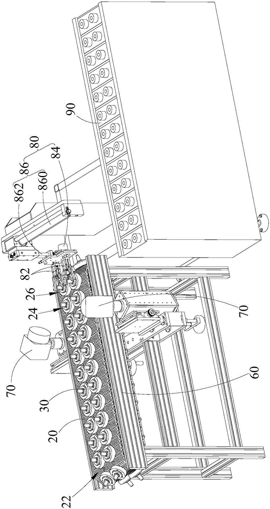
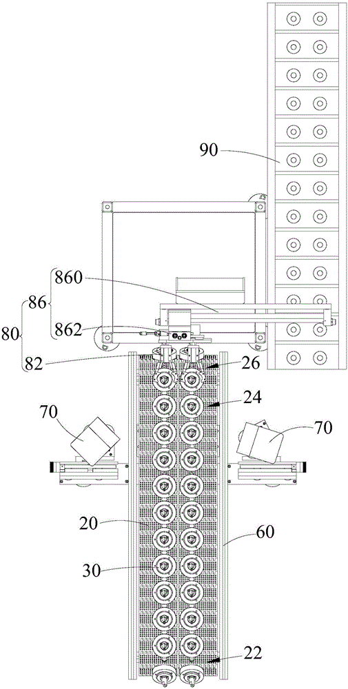
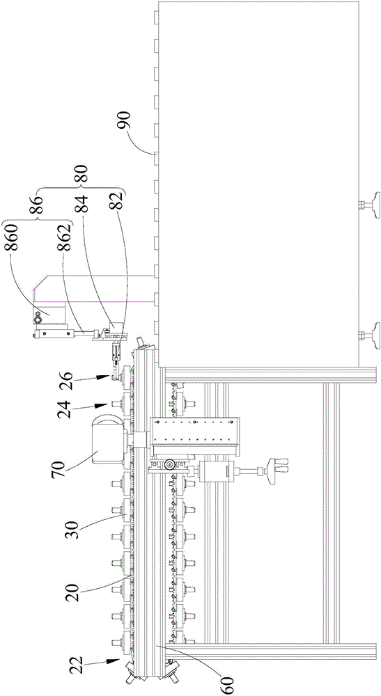
[0053] Please refer to Figure 1 to Figure 9 , The laser marking equipment provided by the embodiment of the present invention includes:

[0054] Frame 60;

[0055] The conveyor belt 20 is installed on the frame 60 for carrying workpieces and driving the workpieces to move in translation. The conveyor belt 20 is sequentially provided with an upper part for placing the workpieces on the conveyor belt 20 along the moving direction of the workpiece. Material station 22, marking station 24 and blanking station 26;

[0056] At least one laser scanning head 70 is installed on the frame 60 and located ...


PUM


Abstract

The present invention is applied to the technology field of a marking device, and provides a laser marking device. The laser marking device comprises a rack, a conveyer belt, at least one laser scanning head, a plurality of bearing seats, a rotating mechanism and a discharging mechanism. The conveyer belt is provided with a loading station, a marking station and an unloading station in the order along the moving direction of workpieces; and the rotating mechanism is configured to drive the workpieces on the bearing seats to rotate in the process of marking. The workpieces at the loading station are disposed onto the bearing seats of the conveyer belt, the marking station is driven by the rotating mechanism to rotate with respect to the bearing seats so as to complete rotary marking in a circumference direction, and the workpieces are moved with the bearing seats and the conveyer belt to the unloading station and are taken away from the bearing seats through the discharging mechanism. In this way, the loading, the rotary marking and the grabbing unloading are synchronously completed, the durations of unloading and waiting for laser rotary marking are greatly shortened and productivity is greatly improved.

Description

Technical field [0001] The invention belongs to the technical field of marking equipment, and particularly relates to a laser marking equipment. Background technique [0002] Laser marking is to use a laser beam to make permanent marks on the surface of various materials. The effect of marking is to expose the deep material through the evaporation of the surface material, or to "carve" traces through the chemical and physical changes of the surface material caused by light energy, or to burn off part of the material through light energy to show the required etching Patterns, text. Laser marking has the advantages of fast marking speed, good continuous working stability, positioning accuracy, etc., and is widely used in the marking of graphics and text in various fields such as electronics, hardware, aerospace devices, auto parts, metal signs, and LEDs. [0003] Laser marking equipment generally consists of a workbench, laser, optical system and control system. The working table ...

Claims


Application Information

Patent Timeline
Patent Type & Authority Applications(China)
IPC IPC(8): B41J2/435B41J11/00
Inventor 蒋丽君杨志画龙传
Owner 深圳市艾雷激光科技有限公司
Why Eureka
Try Eureka