Wireless router for building computer local area network

A wireless router and local area network technology, applied in the field of wireless routers for computer local area network construction, can solve the problems of inconvenient connection, overturning, damage to the wireless router, etc., and achieve the effect of stable installation

Pending Publication Date: 2021-07-13
深圳市四海众联网络科技有限公司
View PDF11 Cites 0 Cited by
  • Summary
  • Abstract
  • Description
  • Claims
  • Application Information

AI Technical Summary

Problems solved by technology

[0005] 1. The above-mentioned wireless router also needs to be connected with an additional power cord, which not only makes the wiring complicated, but also is not convenient enough to connect;
[0006] 2. The above-mentioned wireless routers are not convenient to install and place: the wireless router is box-shaped and needs to be placed on the table or shelf to support it; the wireless router also needs to be connected with network cables, power cables, etc., so the lines around the wireless router are often many and messy. These limits the location where the wireless router can be placed indoors. It can only be placed in places with supports. The signal coverage in these places is often not very good, and it is not convenient for users to use the wireless router. In addition, if the wireless router is placed on a conspicuous area, its messy lines don’t look good enough;
[0007] 3. The above-mentioned wireless router is easy to be tilted due to the traction of the network cable: the wireless router is placed on the table or shelf, and the network cable is gradually extended from the wireless router. Damage to the wireless router;
[0008] 4. The heat dissipation effect of the above-mentioned wireless router is poor: the wireless router is placed on the desktop or shelf, and its bottom is in contact with the desktop or shelf, which seriously affects the heat dissipation of the wireless router. At the same time, the traditional wireless router is not easy to use. External force for heat dissipation

Method used


Image

  • Wireless router for building computer local area network
  • Wireless router for building computer local area network
  • Wireless router for building computer local area network

Examples


Embodiment 1

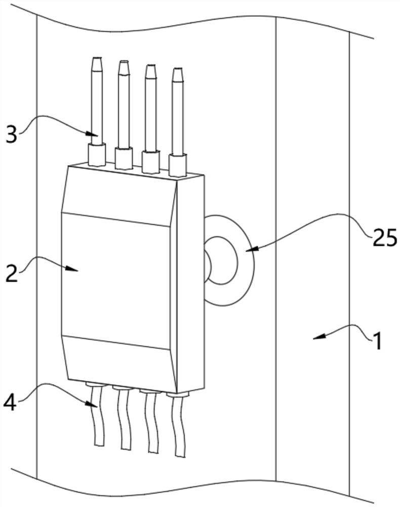
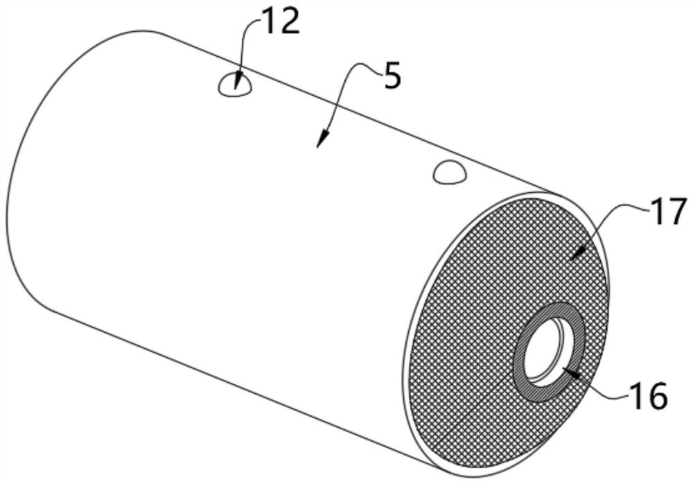
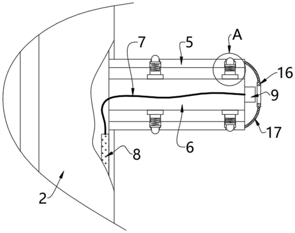
[0043] see figure 1 , image 3 , Figure 5 , Figure 6 and Figure 7 , a wireless router for building a computer local area network, comprising a wall 1 and a wireless router body 2, an installation cylinder 25 is fixedly installed inside the wall 1, a horizontal groove 26 is formed inside the installation cylinder 25, and the back of the wireless router body 2 is fixedly installed The post 5 is plugged in the transverse groove 26, which is more convenient to install, does not take up space on the desktop, and is also more orderly against the wall to prevent the direction of the line.

[0044] The inside of the wireless router body 2 is provided with a circuit control board 8, the outer wall of the circuit control board 8 is fixedly installed with the first connection wire 7, and the power supply device arranged inside the post 5 and the transverse groove 26, when the post 5 is inserted into the transverse groove 26 When it is in the middle, it is used to supply power to t...

Embodiment 2

[0049] see image 3 , Figure 4 and Figure 6 , on the basis of Embodiment 1, the inner wall of the transverse groove 26 is provided with a card slot 18, and the limit device arranged on the outer wall of the post 5 is used to snap into the card slot 18 when the post 5 is inserted into the transverse slot 26 Middle to lock the position of stake 5.

[0050] The limiting device includes an arc-shaped block 12, a pressing plate 13 and a spring 15. A vertical groove 11 is provided through the outer wall of the insertion column 5 and the first pillar 10. The coupled arc-shaped block 12, the bottom of the arc-shaped block 12 is fixedly equipped with a pressing plate 13, the pressing plate 13 is movably arranged on the inner wall of the limiting groove 14, and the limiting groove 14 is opened on the inner wall of the vertical groove 11, and the pressing plate 13 A spring 15 is fixedly installed at the bottom of the bottom, and the spring 15 is fixedly installed on the inner bottom...

Embodiment 3

[0053] see figure 2 , image 3 , Figure 5 and Figure 6 , on the basis of Embodiment 1 and Embodiment 2, a fan 19 is also fixedly installed on the right side of the inner wall of the transverse groove 26, the connector 20 and the post 5 are arranged on the left side of the fan 19, and the outer wall of the wireless router body 2 is uniform A vent is provided, and the fan 19 can blow air into the horizontal groove 26 when it is running. The wind in the horizontal groove 26 enters the inside of the wireless router body 2 through the gap between the post 5 and the inner rod 6, and finally flows from the outer wall of the wireless router body 2. The air vent on the top is discharged, and the heat dissipation effect of the wireless router body 2 can be further improved by utilizing the flow of air. Since the fan 19 is installed on the inwall of the horizontal groove 26, the space inside the wireless router body 2 can not be occupied.

[0054] On the other hand, since the post ...


PUM


Abstract

The invention relates to the technical field of wireless routers, and discloses a wireless router for building a computer local area network. The wireless router comprises a wall body and a wireless router body. An installation cylinder is fixedly installed in the wall body, a transverse groove is formed in the installation cylinder, insertion columns are fixedly installed on the back surface of the wireless router body, and the inserting columns are inserted into the transverse groove. The inserting columns on the back face of the wireless router body are inserted into the transverse groove of the installation cylinder, the wireless router body can be directly installed, installation is more convenient, and when the inserting columns are inserted into the transverse groove, the connecting plugs at the tail ends of the inserting columns are also inserted into the connecting plug bush. At the moment, electric power provided by the power line can be transmitted to the circuit control board through the second connecting line, the connecting plug bush, the connecting plug and the first connecting line, electric power support is provided for the circuit control board, the purpose of automatic energization after installation is achieved, and an additional connecting power source is not needed any more.

Description

technical field [0001] The invention relates to the technical field of wireless routers, in particular to a wireless router for building a computer local area network. Background technique [0002] A wireless router is a bridge between a wired connection and a wireless connection. In companies, homes, and other application environments, we often use wireless routers to build computer local area networks to share data networks. The invention of the wireless router has greatly facilitated people's life and work, and made people's Internet access more convenient. [0003] The Chinese patent announcement number is: CN210444299U utility model patent, which discloses a wireless router for building a computer local area network, including a wireless router main body, a shock-absorbing base and a USB interface end, and a power switch is fixedly connected to the middle part of the wireless router main body. , the bottom of the main body of the wireless router is fixedly connected wi...

Claims


Application Information

Patent Timeline
IPC IPC(8): H04L12/771H04Q1/04H04Q1/02B01D46/10B01D46/00H04L45/60
CPCH04L45/60H04Q1/04H04Q1/035B01D46/10B01D46/76
Inventor 章涛
Owner 深圳市四海众联网络科技有限公司
Why Eureka
Try Eureka