
Automatic assembling equipment for valves special for hot water pipes

An automatic assembly and hot water pipe technology, applied in metal processing equipment, metal processing, manufacturing tools, etc., can solve the time-consuming and labor-intensive problems of hot water pipe valve assembly, to solve the time-consuming and labor-intensive assembly, reduce human labor, and improve assembly efficiency Effect

Inactive Publication Date: 2021-07-16
罗玉琴
View PDF6 Cites 3 Cited by
  • Summary
  • Abstract
  • Description
  • Claims
  • Application Information

AI Technical Summary

Problems solved by technology

[0005] In order to solve the above technical problems, an automatic assembly equipment for hot water pipe valves is provided. This technical solution solves the time-consuming and labor-intensive problem of traditional manual assembly of hot water pipe valves.

Method used


Image

  • Automatic assembling equipment for valves special for hot water pipes
  • Automatic assembling equipment for valves special for hot water pipes
  • Automatic assembling equipment for valves special for hot water pipes

Examples


Embodiment Construction

[0079] The following description serves to disclose the present invention to enable those skilled in the art to carry out the present invention. The preferred embodiments described below are only examples, and those skilled in the art can devise other obvious variations.

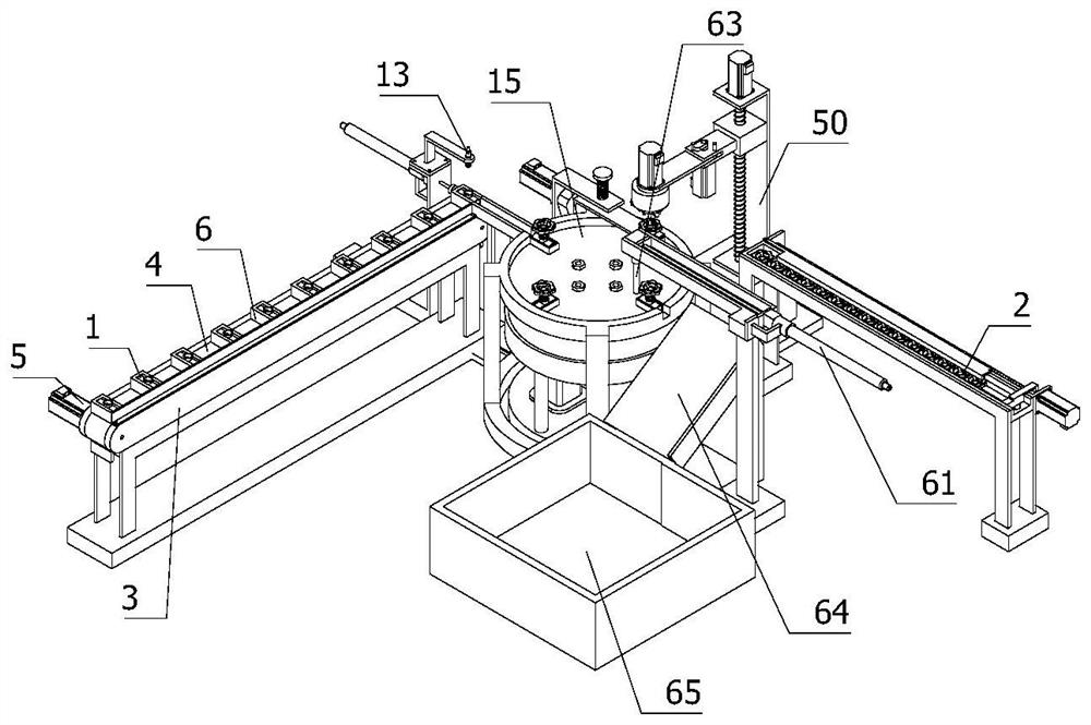
[0080] refer to Figure 1 to Figure 10 As shown, a special valve automatic assembly equipment for hot water pipes, including:

[0081] Rotary feeding assembly, used to rotate the valve core 1 to the runner 2;

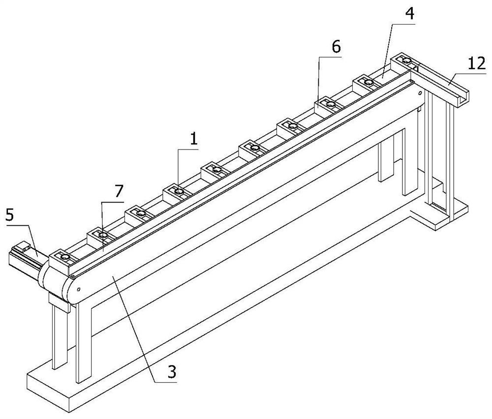
[0082] The conveying assembly is used to convey the valve core 1 of the batch, and the conveying assembly is arranged on the side of the rotating feeding assembly;

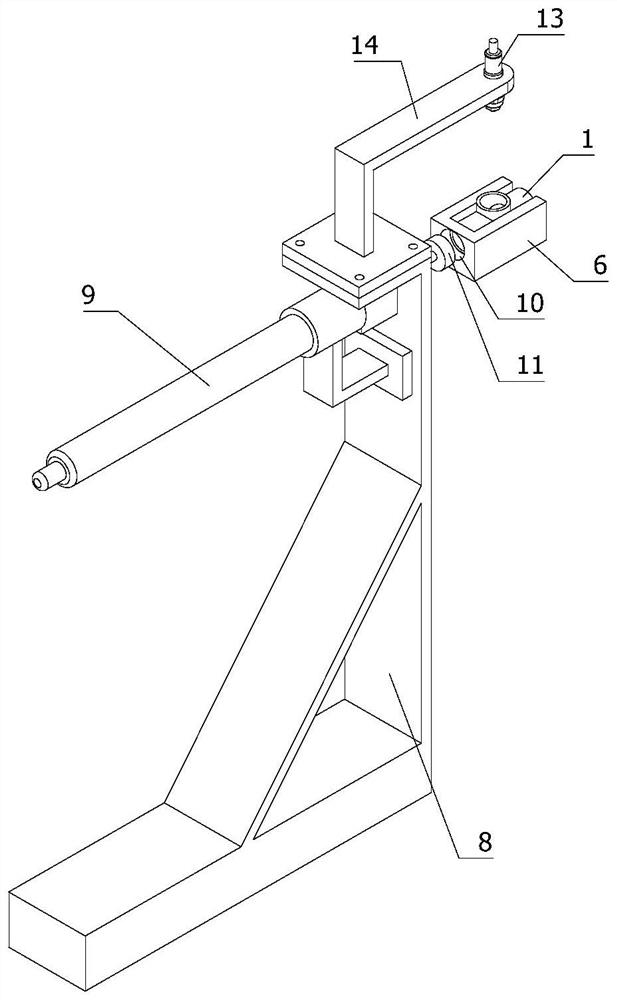
[0083] The pushing assembly is used to push the valve core 1 on the conveying assembly to the rotating feeding assembly. The pushing assembly is arranged on the side of the conveying assembly away from the rotating feeding assembly. The pushing direction of the pushing assembly is also perpendicular to the conveying of the conveying ass...


PUM


Abstract

The invention relates to the field of automatic assembling, in particular to automatic assembly equipment for valves special for hot water pipes. The automatic assembly equipment comprises a rotary feeding assembly, a conveying assembly, a material pushing assembly, a downward pressing assembly, an assembling assembly, a material moving assembly and a material unloading assembly, wherein the rotary feeding assembly is used for rotatably conveying valve cores to rotating wheels; the conveying assembly is used for conveying the batch valve cores; the material pushing assembly is used for pushing the valve cores on the conveying assembly onto the rotary feeding assembly; the downward pressing assembly is used for firmly positioning the valve cores to the rotary feeding assembly when the valve cores and the rotating wheels are assembled; the assembling assembly is used for assembling the rotating wheels to the valve cores in a threaded mode; the material moving assembly is used for conveying the batch rotating wheels to the side of the assembling assembly, and the material moving direction of the material moving assembly is further perpendicular to the conveying direction of the conveying assembly; and the material unloading assembly is used for sending out the assembled valves integrally, and the material unloading assembly is arranged on the side, away from the material pushing assembly, of the rotary feeding assembly. By means of the automatic assembly equipment for the valves special for the hot water pipes, the problem that time and labor are wasted when the hot water pipe valves are assembled manually in the prior art is solved, the manual labor is reduced, and the hot water pipe valve assembling efficiency is improved.

Description

technical field [0001] The invention relates to the field of automatic assembly, in particular to an automatic assembly device for a special valve for hot water pipes. Background technique [0002] Valves are the control components in the fluid delivery system. They have the functions of cut-off, adjustment, flow diversion, reverse flow prevention, pressure stabilization, flow diversion or overflow pressure relief. Valves used in fluid control systems range from the simplest cut-off valve to extremely complex The various valves used in the automatic control system have a wide variety of varieties and specifications. The valves can be used to control the flow of various types of fluids such as air, water, steam, various corrosive media, mud, oil, liquid metal and radioactive media. The threaded assembly of the valve mainly refers to the threaded assembly between the valve body and the valve cover. The valve body also includes a ball and an elastic gasket. Therefore, when the ...

Claims


Application Information

Patent Timeline
Patent Type & Authority Applications(China)
IPC IPC(8): B23P19/04B23P19/00
CPCB23P19/04B23P19/00
Inventor 罗玉琴
Owner 罗玉琴
Learn More