
Evaporation source

A technology of evaporation source and cooling box, which is applied in the field of evaporation source, can solve the problems of low manufacturing efficiency of display panel, low evaporation efficiency, and high cost, and achieve the effects of ensuring temperature, improving evaporation efficiency, and improving product quality

Pending Publication Date: 2021-07-16
SHANGHAI SHINSEE OPTOELECTRONICS TECH CO LTD
View PDF0 Cites 0 Cited by
  • Summary
  • Abstract
  • Description
  • Claims
  • Application Information

AI Technical Summary

Problems solved by technology

However, the evaporation efficiency of the existing evaporation source equipment is low, and the evaporation of multiple materials at the same time has mutual doping, which leads to problems such as low manufacturing efficiency, low quality rate, and high cost of the display panel.

Method used


Image

  • Evaporation source
  • Evaporation source
  • Evaporation source

Examples


Embodiment Construction

[0052] The technical solutions of the present invention will be clearly and completely described below through specific embodiments in conjunction with the accompanying drawings. Obviously, the described embodiments are part of the embodiments of the present invention, but not all of them. Based on the embodiments of the present invention, all other embodiments obtained by persons of ordinary skill in the art without making creative efforts belong to the protection scope of the present invention.

[0053] In the description of the present invention, it should be noted that the orientation or positional relationship indicated by the terms "inner", "outer" and the like are based on the orientation or positional relationship shown in the drawings, and are only for the convenience of describing the present invention and simplifying the description. It is not intended to indicate or imply that the referred device or element must have a particular orientation, be constructed in a par...


PUM


Abstract

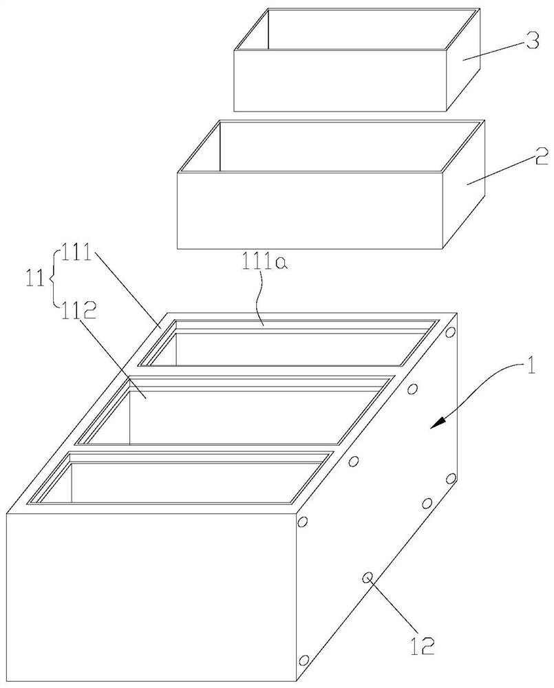
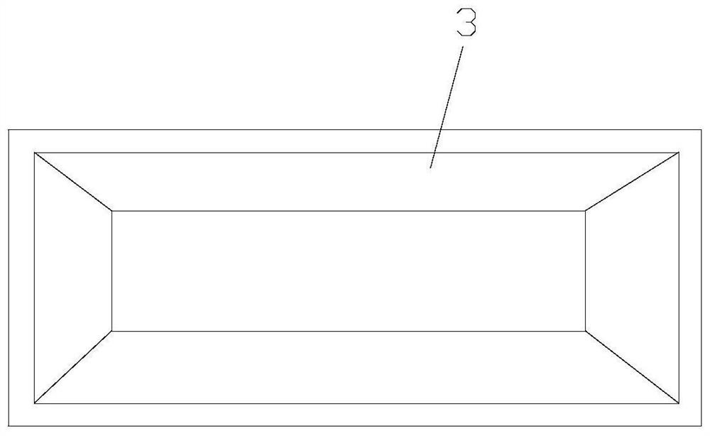
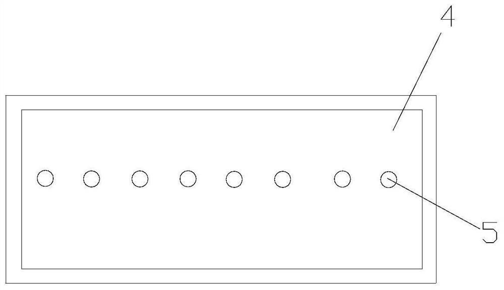
The invention relates to the technical field of display equipment, in particular to an evaporation source. The evaporation source comprises a cooling device, a heating device and a plurality of crucibles, wherein the cooling device comprises a cooling box and a cooling assembly, the cooling box is provided with a plurality of independent assembling grooves, the crucibles are arranged in the assembling grooves in a one-to-one correspondence mode, the cooling assembly is located on the cooling box, the heating device is located in the cooling box, the cooling assembly is arranged to cool the cooling box, and the heating device is arranged to heat the crucibles. The evaporation source provided by the invention can be used for evaporation of various materials, and meanwhile, mutual doping among different materials is avoided.

Description

technical field [0001] The invention relates to the technical field of display devices, in particular to an evaporation source. Background technique [0002] OLED (Organic Light-Emitting Diode, that is, organic electroluminescent device) display technology is becoming more and more perfect, and its market popularization has become a trend. Each film layer that constitutes an organic electroluminescent device is generally formed by vacuum evaporation coating. The basic principle of vacuum evaporation coating is to place the coating material in the evaporation source of the evaporation device for heating and evaporation, and the gas molecules or atoms of the formed coating material are deposited on the A film layer is formed on the substrate to be coated. [0003] Although the evaporation source of the existing evaporation device can be used for the production of organic electroluminescent devices, in order to meet the requirements of high-resolution display and large-scale d...

Claims


Application Information

Patent Timeline
IPC IPC(8): C23C14/26
CPCC23C14/243C23C14/26
Inventor 轩景泉林文晶马晓宇
Owner SHANGHAI SHINSEE OPTOELECTRONICS TECH CO LTD
Learn More