
A brake safety locking mechanism

A safe locking and locking technology, applied in the direction of gear transmission mechanism, brake actuator, mechanical equipment, etc., to achieve the effect of convenient operation, simple structure and increased locking torque

Active Publication Date: 2022-05-24
BEIJING SURGERII TECH CO LTD
View PDF5 Cites 0 Cited by
  • Summary
  • Abstract
  • Description
  • Claims
  • Application Information

AI Technical Summary

Problems solved by technology

[0002] The locking of rotary motion mechanism is a common mechanical problem. Although there are many kinds of brake devices, there are few brake devices that can achieve high torque braking in a very limited volume.

Method used


Image

  • A brake safety locking mechanism
  • A brake safety locking mechanism
  • A brake safety locking mechanism

Examples


Embodiment Construction

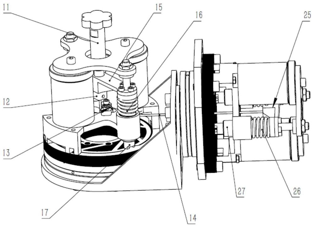
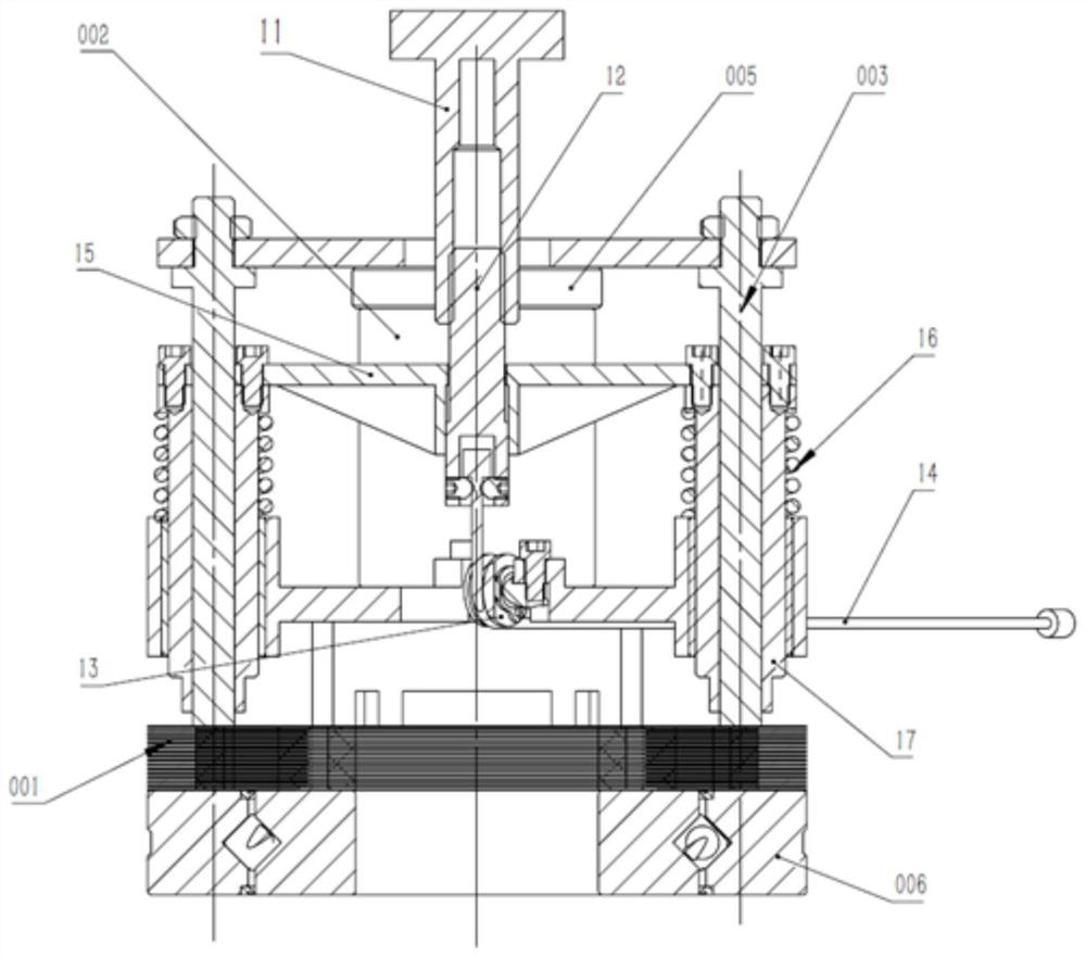
[0027] The preferred embodiments of the present invention will be described in detail below with reference to the accompanying drawings, so as to more clearly understand the objects, features and advantages of the present invention. It should be understood that the embodiments shown in the accompanying drawings are not intended to limit the scope of the present invention, but are only intended to illustrate the essential spirit of the technical solutions of the present invention.

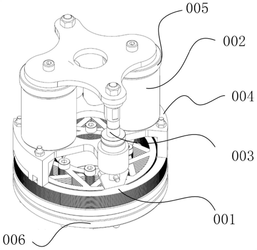
[0028] figure 1 The multi-layer joint stop brake device using electromagnets is shown. The brake device mainly consists of multi-layer 001, electromagnet 002, ejector rod 003, cage 004, anti-suction steel block 005 and crossed roller bearing 006 etc. composition. Among them, the inner and outer rings of the multi-layer 001 are in contact with the inner and outer rings of the crossed roller bearing 006, respectively. Part of the inner and outer rings of the multi-layer 001 overlap but there is a sma...


PUM


Abstract

The invention relates to a safety locking mechanism for a brake, comprising: an additional locking component, located above multiple layers of the brake device and movably arranged on a push rod of the brake device; a starting component, and an additional locking component connected to drive the additional locking component to move axially along the ejector rod; when the activation component drives the additional locking component to move toward the direction close to the multi-layer, the additional locking component compresses the multi-layer; when the activation component drives When the additional locking component moves away from the multi-sheet layer, the additional locking component releases the multi-sheet layer. The present invention is simple in structure, easy to realize, and the risk of purely mechanical structure failure is small, and only the safety locking mechanism can be used as a manual locking mechanism without using an electromagnet, so that the stop brake device can be used even when the electromagnet It can still be used in the event of a failure, and can avoid the risk of overall structural failure caused by a single failure of the brake device on important occasions.

Description

technical field [0001] The invention relates to a locking mechanism for a holding brake, in particular to a safety locking mechanism for a multi-layer joint-stopping holding brake device using an electromagnet. Background technique [0002] The locking of the rotary motion mechanism is a common mechanical problem. Although there are many kinds of brake devices at present, there are few brake devices that can realize high-torque braking in a very limited volume. Beijing Shurui Technology Co., Ltd. has developed a multi-layer joint locking brake device using electromagnets, and has applied for a national invention patent (publication number: CN109386557A). The locking brake device can occupy a small space. High torque locking at any rotational position is achieved without [0003] However, this kind of locking brake device has high requirements on the multi-layer gap and the machining accuracy of some parts, and there is a possibility of insufficient locking force in the case...

Claims


Application Information

Patent Timeline
Patent Type & Authority Patents(China)
IPC IPC(8): F16D65/14F16D121/14F16D121/20F16D127/06
CPCF16D65/14F16D2121/14F16D2121/20F16D2127/06
Inventor 徐凯其他发明人请求不公开姓名
Owner BEIJING SURGERII TECH CO LTD
Learn More