Calibration method for dynamic test of detecting wheel

A technology of dynamic testing and calibration methods, which is applied to measuring devices, material analysis using sound waves/ultrasonic waves/infrasonic waves, instruments, etc., can solve problems such as the inability to judge the state of the probe wheel, and the inability to use calibration and calibration methods to achieve fast flaw detection operations. Effect

Active Publication Date: 2021-07-16
GUANGDONG GOWORLD
View PDF3 Cites 1 Cited by
  • Summary
  • Abstract
  • Description
  • Claims
  • Application Information

AI Technical Summary

Problems solved by technology

[0004] However, since the bracket of the probe wheel has been installed inside the wheel skin during the dynamic index test of the probe wheel, and the wheel skin has been filled with coupling fluid, it is impossible to judge the state of each probe in the probe wheel with the naked eye. Due to site constraints, it is not possible to use the calibration method in an ideal indoor environment (such as a laboratory environment)

Method used


Image

  • Calibration method for dynamic test of detecting wheel
  • Calibration method for dynamic test of detecting wheel
  • Calibration method for dynamic test of detecting wheel

Examples


Embodiment Construction

[0024] Further description will be given below in conjunction with the accompanying drawings and preferred embodiments of the present invention.

[0025] This embodiment provides a calibration method for dynamic testing of probe wheels, which includes the following steps:

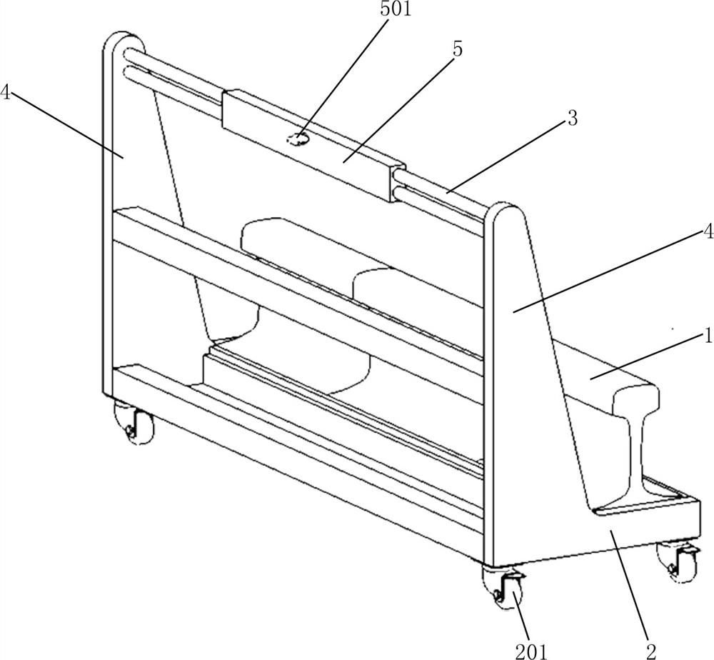
[0026] Step 1: Fix the test block 1 on the test block frame, and then delineate the center line of the test block 1 along its axial direction on the upper surface of the test block 1;

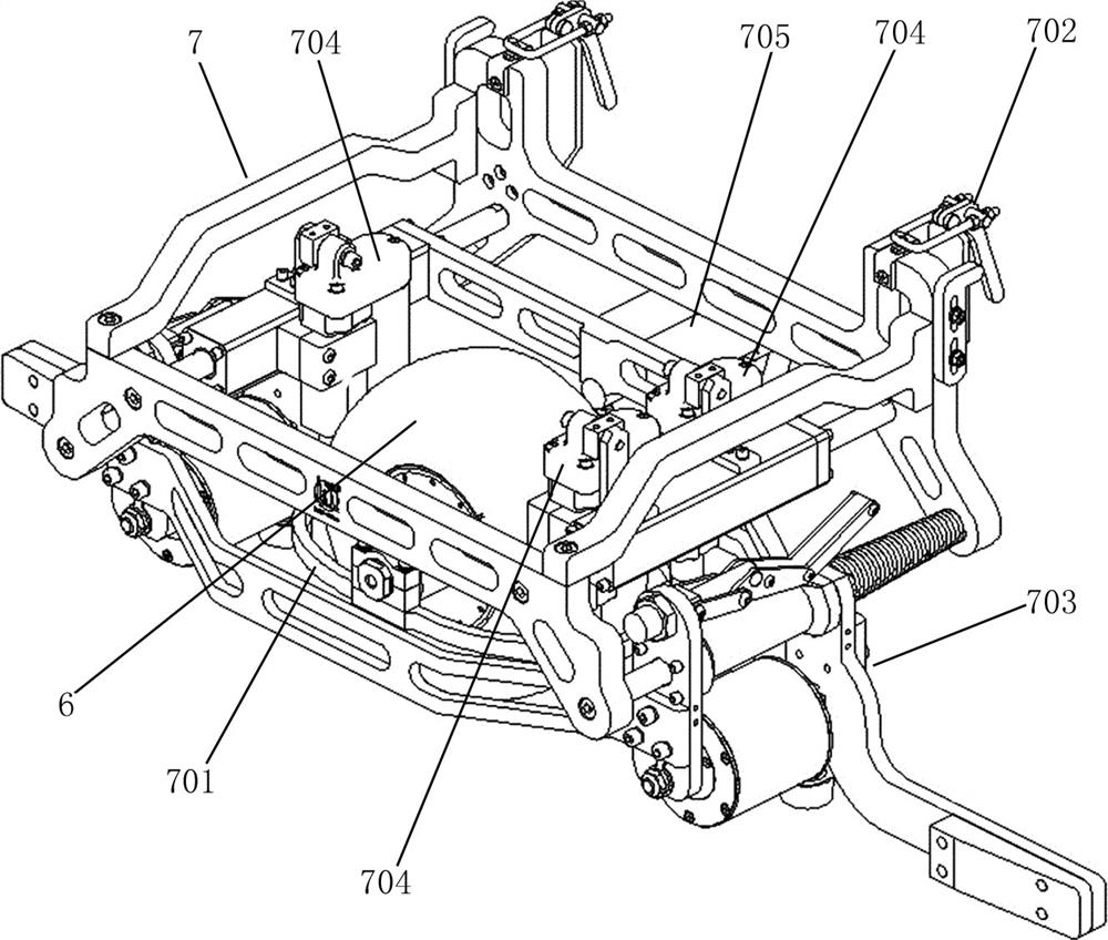
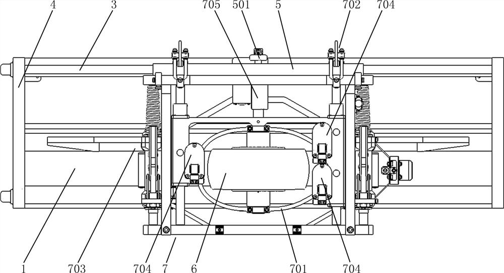
[0027] Step 2: Delineate the centerline of the wheel surface of the wheel 6 along its circumference on the wheel surface of the wheel 6, and then install the wheel 6 on the fixed bracket 701 of the wheel frame 7;

[0028] Step 3: Install the wheel frame 7 on the test block frame so that the wheel surface of the wheel 6 fits the rail surface of the test block 1, and the wheel frame 7 can move along the extension direction of the test block 1;

[0029] Step 4: Adjust the position of the probe wheel 6 through the probe wheel f...


PUM


Abstract

The invention relates to a calibration method for a dynamic test of a detection wheel, which comprises the following steps: multiple echo waveforms of a 0-degree normal probe are read, and through moving the detection wheel on a test block and adjusting the relative position of the detection wheel and the upper surface of the test block, multiple echo waveforms of the 0-degree normal probe and related performance indexes displayed on the test instrument accord with a preset calibration parameter range; according to ideal conditions, the 0-degree normal probe is arranged in the middle of all the probes and located in the same vertical plane with the center line, the 0-degree normal probe is vertically aligned with the center line of the steel rail in the ideal scanning process, and all horizontal cracks can be detected, so that the 0-degree normal probe is selected for dynamic detection of the detection wheel, and the center line of the wheel surface of the detection wheel is aligned with the center line of the upper surface of the test block at the beginning of the test so as to be used as a standard position for calibration, and the detection wheel can be quickly, conveniently and accurately calibrated only by observing multiple echo waveforms of the 0-degree normal probe.

Description

technical field [0001] The invention relates to the technical field of ultrasonic flaw detection, in particular to a calibration calibration method for dynamic testing of probe wheels. Background technique [0002] As the detection part of the rail flaw detection vehicle, the detection wheel is based on the principle of ultrasonic flaw detection, using a combination of different types of probes, adding a special polyurethane material to make the wheel skin, and filling the entire wheel with coupling fluid as a conductive medium. Flaw detection equipment, its main function is to detect the specified artificial damage on the rail, that is, the dynamic index test of the detection wheel. There are nine single probes installed on the same bracket in the rail probe wheel, including a 0° straight probe, two 37° angled probes and six 70° angled probes. The 37° probes and 70° probes are placed symmetrically. The positions of the rail bottom, screw hole, rail head and lower jaw of th...

Claims


Application Information

Patent Timeline
Patent Type & Authority Applications(China)
IPC IPC(8): G01N29/30
CPCG01N29/30G01N2291/0234G01N2291/0289G01N2291/2623
Inventor 陈志佳丁旭升陈伟杰马泽雄吴金林周少武陈坤裕许燚楷郑燕峰李佳
Owner GUANGDONG GOWORLD
Why Eureka
Try Eureka