Check patentability & draft patents in minutes with Patsnap Eureka AI!

Stress-induced high-birefringence super-large mode field photonic crystal fiber

A technology of photonic crystal fiber and high birefringence, which is applied in polarizing fiber, cladding fiber, optical waveguide and light guide, etc. It can solve the problem of difficult to achieve high birefringence polarization-maintaining photonic crystal fiber and photonic crystal fiber are difficult to achieve fiber single-mode transmission and other problems, to achieve the effect of easy operation and increasing the limit loss ratio

Active Publication Date: 2021-07-16
XI'AN INST OF OPTICS & FINE MECHANICS - CHINESE ACAD OF SCI
View PDF7 Cites 0 Cited by
  • Summary
  • Abstract
  • Description
  • Claims
  • Application Information

AI Technical Summary

Problems solved by technology

[0011] The purpose of the present invention is to solve the technical problem that photonic crystal fiber is difficult to realize the single-mode transmission of ultra-large mode field area fiber, and it is difficult to realize the polarization-maintaining photonic crystal fiber with high birefringence value under the condition of large mode field area transmission. Realization of high birefringence ultra-large mode field photonic crystal fiber

Method used


Image

  • Stress-induced high-birefringence super-large mode field photonic crystal fiber
  • Stress-induced high-birefringence super-large mode field photonic crystal fiber
  • Stress-induced high-birefringence super-large mode field photonic crystal fiber

Examples


Embodiment 1

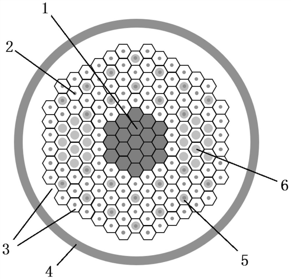
[0088] The 19 air hole positions are replaced by the core 1, the high-order mode filtering structure 5 is added, and the stress material introduced into the stress zone 6 is a boron rod. The structure of the photonic crystal fiber is as follows figure 1 shown.

[0089] 1) PCF fiber structure parameters:

[0090] Air hole diameter d=1~5μm, hole spacing Λ=14.5~25μm, d / Λ=0.04~0.5; fiber core 1 replaces three layers of air holes, that is, silica with 19 air holes; fiber core 1 has six Polygonal shape, so that there is no gap in the fiber arrangement when the fiber is drawn, the edge is equal to 5 / 2Λ, and the core diameter is 5.5Λ;

[0091] The air hole cladding around the fiber core 1 has five layers of air holes 2, the cladding base 3 is silicon dioxide, and the air holes 2 are arranged in a triangular lattice structure; a high-order mode filter structure 5 is added to the air hole cladding, and the high-order mode filter The filter structure 5 is composed of a plurality of ann...

Embodiment 2

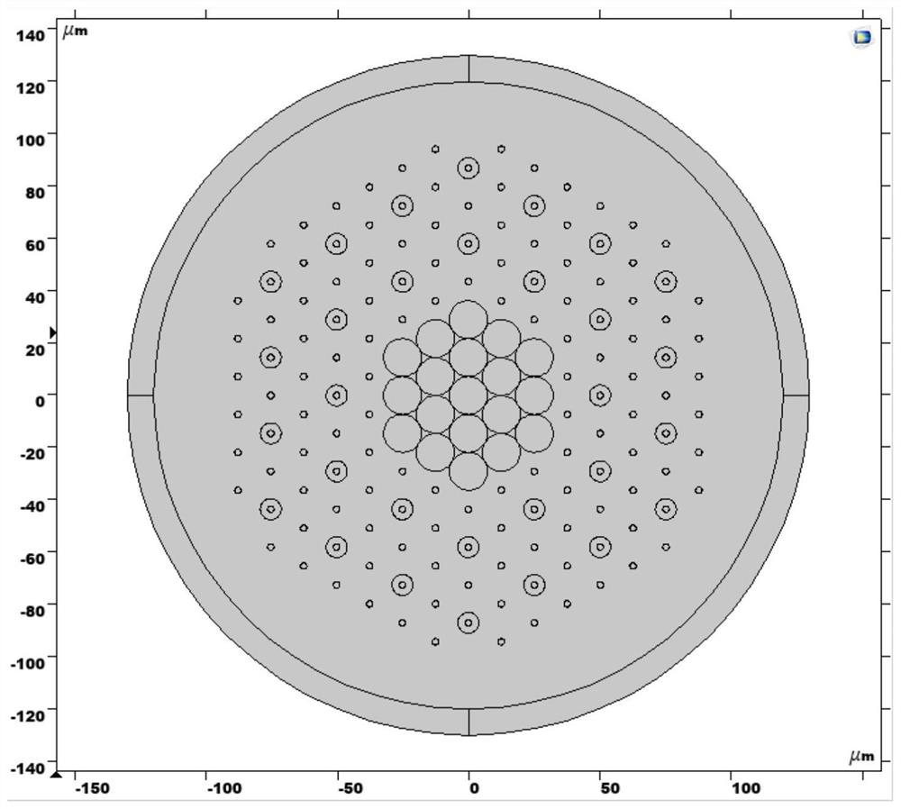
[0111] The 19 air holes are replaced by the core 1, and the stress material introduced into the stress zone 6 is a boron rod. The structure of the photonic crystal fiber is as follows Image 6 shown.

[0112] 1) PCF fiber structure parameters:

[0113] Air hole diameter d=1~5μm, hole spacing Λ=14.5~25μm, d / Λ=0.04~0.5; fiber core 1 replaces three layers of air holes, that is, silica with 19 air holes; fiber core 1 has six Hexagonal shape, when the fiber is drawn, the fiber arrangement has no gaps, the edge is equal to 5 / 2Λ, and the core diameter is 5.5Λ;

[0114] The air hole cladding around the fiber core 1 has five layers of air holes 2, the cladding base 3 is silicon dioxide, and the air holes 2 have a triangular lattice layout structure;

[0115] The boron rod introduced into the stress zone 6 in the air hole cladding includes a boron rod core and a quartz outer layer. The diameter of the boron rod core is D = 12-15 μm. The larger the number of boron rods, the better the ...


PUM

PropertyMeasurementUnit
Thermal expansion coefficientaaaaaaaaaa
Outer diameteraaaaaaaaaa
Diameteraaaaaaaaaa

Abstract

The invention relates to a photonic crystal fiber, particularly relates to a stress-induced high-birefringence super-large-mode-field photonic crystal fiber, and aims to solve technical problems that single-mode transmission of a super-large-mode-field-area fiber is difficult to realize by the photonic crystal fiber, and a polarization-maintaining photonic crystal fiber with a high birefringence value is difficult to realize under the condition of large-mode-field-area transmission. The crystal fiber comprises a fiber core, an air hole wrapping layer and a perfect matching layer, and further comprises a high-order mode filtering structure and a stress area which are arranged in the air hole wrapping layer, wherein the fiber core structurally replaces the positions of 19 air holes; the air holes in the air hole cladding meet the following condition: d / lambda = 0.04-0.5; the high-order mode filtering structure comprises a plurality of annular structures arranged outside the corresponding air holes; two stress areas which are symmetrically distributed relative to the fiber core are arranged, and each stress area is composed of m boron rods. The photonic crystal fiber provided by the invention can realize single-mode transmission in an ultra-large mode field area with a mode field diameter greater than or equal to 60 [mu] m, and the polarization-maintaining performance of a birefringence value greater than 10 <-4 > magnitude is realized.

Description

technical field [0001] The invention relates to a photonic crystal fiber, in particular to a stress-induced high birefringence ultra-large mode field photonic crystal fiber. Background technique [0002] Conventional circularly symmetric fibers do not maintain the polarization state of the guided modes along their length. Although nominally isotropic, small twists, bends, and other stresses impose unknown and uncontrollable birefringence on the fiber, so the polarization of the fiber output is unpredictable. In the fiber manufacturing process, strong birefringence is deliberately introduced to achieve high birefringence values, making the fiber more controllable to these environmental factors. For traditional polarization maintaining fiber, although its birefringence value can reach higher than 10 -4 The order of magnitude, but its single-mode mode field diameter is too small to meet the requirements of high-power fiber lasers. [0003] Compared with traditional optical f...

Claims


Application Information

Patent Timeline
IPC IPC(8): G02B6/02G02B6/024G02B1/00
CPCG02B6/02014G02B6/02009G02B6/02342G02B6/02357G02B6/024G02B1/005
Inventor 马园王鹏飞彭波
Owner XI'AN INST OF OPTICS & FINE MECHANICS - CHINESE ACAD OF SCI
Features
  • R&D
  • Intellectual Property
  • Life Sciences
  • Materials
  • Tech Scout
  • Unparalleled Data Quality
  • Higher Quality Content
  • 60% Fewer Hallucinations
Learn More