A high-efficiency heat-conducting heat pipe reactor fuel element

A fuel element and reactor technology, which is applied in the reactor-related fields, can solve the problems of reducing the share of nuclear fuel, low thermal conductivity, unfavorable small and lightweight design of the reactor, etc.

Active Publication Date: 2022-04-12
安徽中科超核科技有限公司
View PDF0 Cites 0 Cited by
  • Summary
  • Abstract
  • Description
  • Claims
  • Application Information

AI Technical Summary

Problems solved by technology

[0002] The heat pipe reactor is currently a reactor with good prospects for space nuclear power applications. The passive heat conduction of nuclear fuel with heat pipes is a hot spot in foreign space nuclear power research. The existing nuclear fuel is UO 2 Mainly, the thermal conductivity is low, which is the bottleneck restricting the increase of power density and the reduction of volume and weight of the reactor. The share of nuclear fuel is reduced, which is not conducive to the small and lightweight design of the reactor

Method used


Image

  • A high-efficiency heat-conducting heat pipe reactor fuel element
  • A high-efficiency heat-conducting heat pipe reactor fuel element
  • A high-efficiency heat-conducting heat pipe reactor fuel element

Examples


Embodiment 1

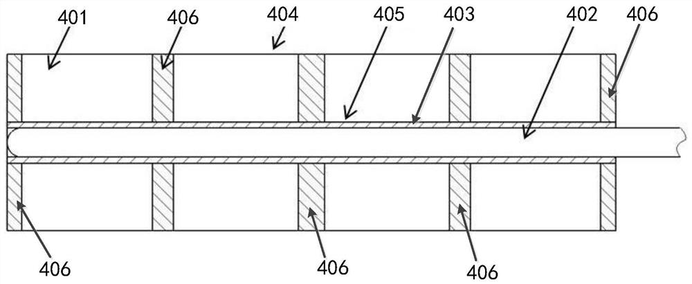
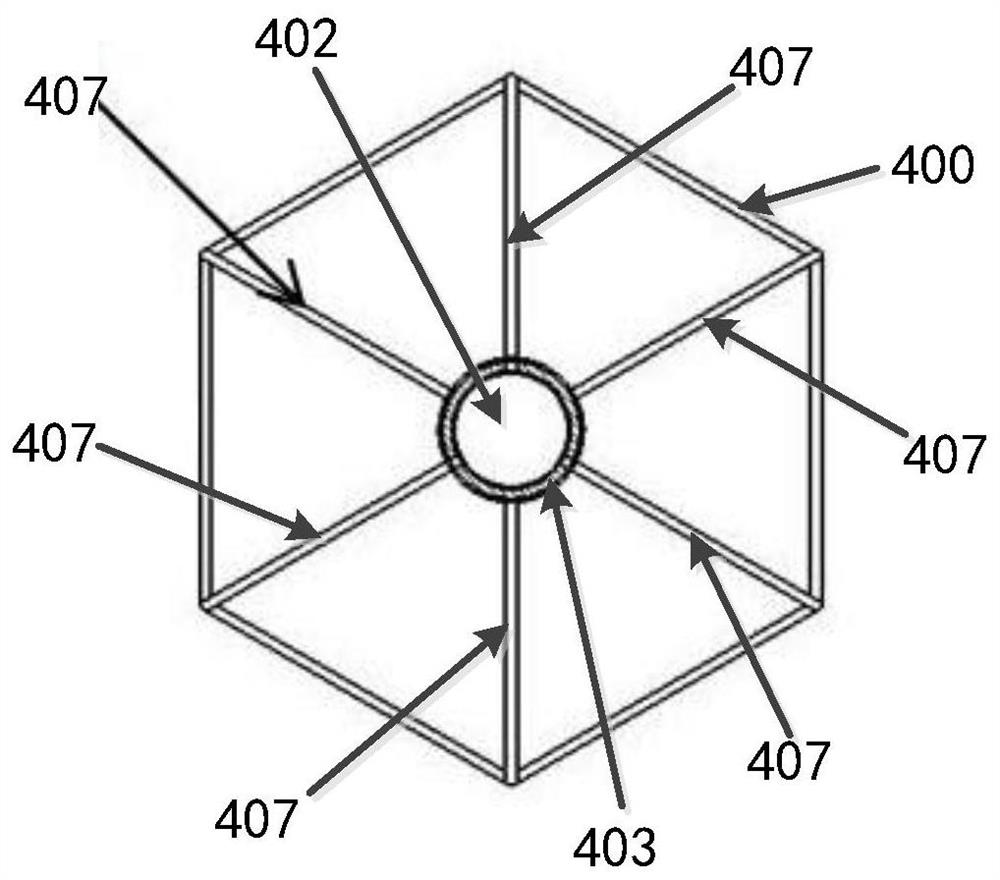
[0030] like Figure 1-Figure 3 As shown, a high-efficiency heat-conducting heat pipe reactor fuel element in this embodiment includes a nuclear fuel 401, a cladding tube 400, a heat pipe 402, and a heat-conducting ring 403. The cladding tube 400 includes a sleeved inner wall 405 and an outer wall 404, so The heat pipe 402 is placed in the inner hole of the inner wall 405, the heat conduction ring 403 is sleeved outside the heat pipe 402 and is located between the heat pipe 402 and the inner wall 405; the inner wall 405 of the cladding tube 400 A number of axial heat conduction plates 407 and a number of radial heat conduction plates 406 are arranged between the outer wall 404, and the axial heat conduction plates 407 and radial heat conduction plates 406 divide the cladding tube 400 into several for filling the nuclear fuel In the fuel area of ​​401 , stress relief grooves 408 are opened on the axial heat conducting plate 407 .

[0031] In the high-efficiency heat-conducting ...

Embodiment 2

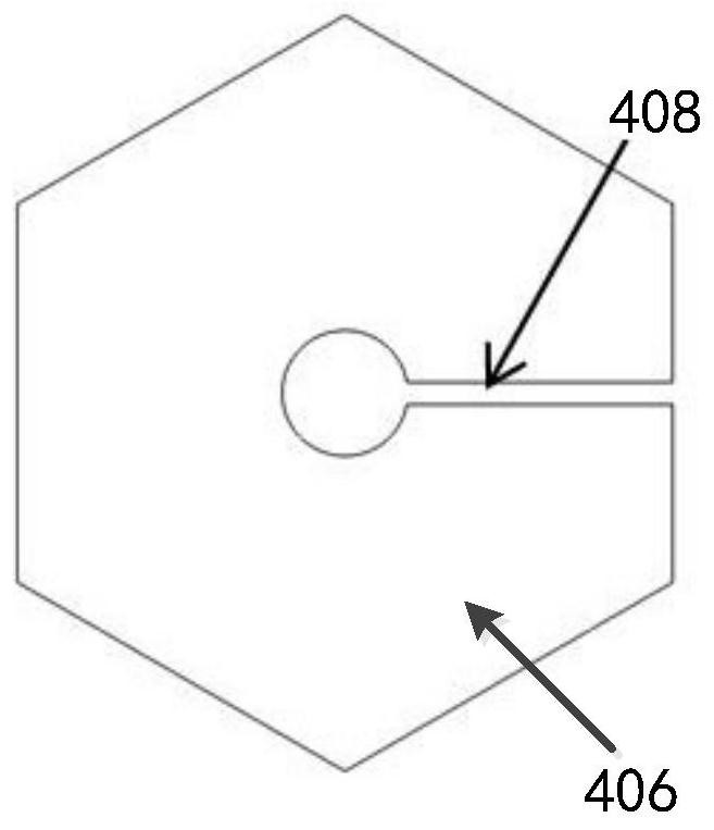
[0033] like Figure 1-Figure 3 As shown, a high-efficiency heat-conducting heat pipe reactor fuel element in this embodiment includes a nuclear fuel 401, a cladding tube 400, a heat pipe 402, and a heat-conducting ring 403. The cladding tube 400 includes a sleeved inner wall 405 and an outer wall 404, so The heat pipe 402 is placed in the inner hole of the inner wall 405, the heat conduction ring 403 is sleeved outside the heat pipe 402 and is located between the heat pipe 402 and the inner wall 405; the inner wall 405 of the cladding tube 400 A number of axial heat conduction plates 407 and a number of radial heat conduction plates 406 are arranged between the outer wall 404, and the axial heat conduction plates 407 and radial heat conduction plates 406 divide the cladding tube 400 into several for filling the nuclear fuel In the fuel area of ​​401 , stress relief grooves 408 are opened on the radial heat conduction plate 406 .

[0034] like image 3 As shown, the stress re...


PUM


Abstract

The invention relates to a high-efficiency heat-conducting heat pipe reactor fuel element. The fuel element includes nuclear fuel, a cladding tube, a heat pipe and a heat-conducting ring. The cladding tube includes an inner wall and an outer wall sheathed. The ring is set outside the heat pipe and between the heat pipe and the inner wall; there are several axial heat conduction plates and some radial heat conduction plates between the inner wall and the outer wall of the cladding tube, and the axial guide plates and radial guide plates guide the cladding tube It is divided into several fuel areas for filling the nuclear fuel, and stress relief grooves are opened on the axial guide plate. In the high-efficiency heat-conducting heat pipe reactor fuel element of the present invention, the nuclear fuel is placed inside the cladding tube, and the nuclear heat generated during operation is transferred to the heat pipe through the cladding tube wall; axial and radial heat conduction plates are arranged in the cladding tube to assist in high-efficiency heat conduction The heat pipe is arranged at the center of the fuel element to export the core heat out of the stack; the heat conduction ring is arranged between the heat pipe and the cladding tube to realize the contact heat transfer between the heat pipe and the cladding.

Description

technical field [0001] The invention relates to the technical field related to reactors, in particular to a high-efficiency heat conduction heat pipe reactor fuel element. Background technique [0002] The heat pipe reactor is currently a reactor with good prospects for space nuclear power applications. The passive heat conduction of nuclear fuel with heat pipes is a hot spot in foreign space nuclear power research. The existing nuclear fuel is UO 2 Mainly, the thermal conductivity is low, which is the bottleneck restricting the increase of power density and the reduction of volume and weight of the reactor. The share of nuclear fuel is reduced, which is not conducive to the small and lightweight design of the reactor. Contents of the invention [0003] The technical problem to be solved by the present invention is to provide a high-efficiency heat-conducting heat pipe reactor fuel element for the deficiencies of the prior art. [0004] The technical solution of the pres...

Claims


Application Information

Patent Timeline
Patent Type & Authority Patents(China)
IPC IPC(8): G21C3/08G21C3/06
CPCG21C3/08G21C3/06Y02E30/30
Inventor 不公告发明人
Owner 安徽中科超核科技有限公司
Why Eureka
Try Eureka