a discharge device

A technology of discharge device and discharge part, which is applied to switch devices, electrical components, etc., can solve the problems of short circuit of positive and negative electrodes of capacitors and grounding discharge, physical strain of maintenance personnel, low discharge efficiency, etc., so as to improve discharge operation efficiency, The effect of reducing physical strain and improving discharge efficiency

Active Publication Date: 2022-04-12
GUANGDONG POWER GRID CO LTD +1
View PDF5 Cites 0 Cited by
  • Summary
  • Abstract
  • Description
  • Claims
  • Application Information

AI Technical Summary

Problems solved by technology

[0003] When discharging capacitors in existing substations, a discharge rod or ordinary grounding wire is generally used to directly discharge the positive and negative terminals of the capacitor for multiple times, and only one terminal of the capacitor is discharged each time. The positive and negative poles are short-circuited and discharged to the ground, the workload is heavy and it is easy to cause physical strain to the maintenance personnel
At the same time, when the current discharge device discharges the capacitor, in order to ensure that the discharge conductor is in contact with the capacitor terminal, the maintenance personnel must press the insulating rod against the capacitor terminal with force, resulting in laborious operation and low discharge efficiency.

Method used


Image

  • a discharge device
  • a discharge device
  • a discharge device

Examples


Embodiment 1

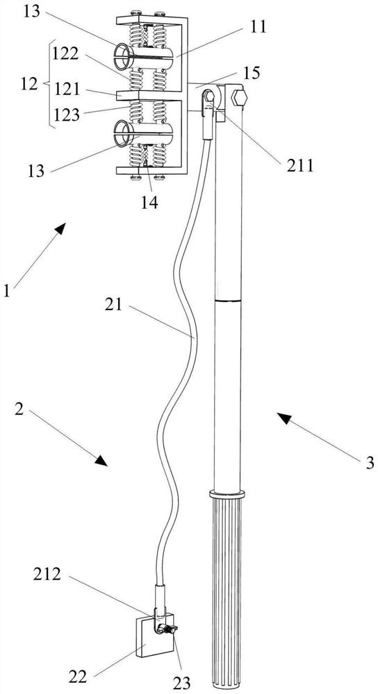
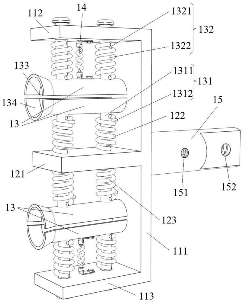
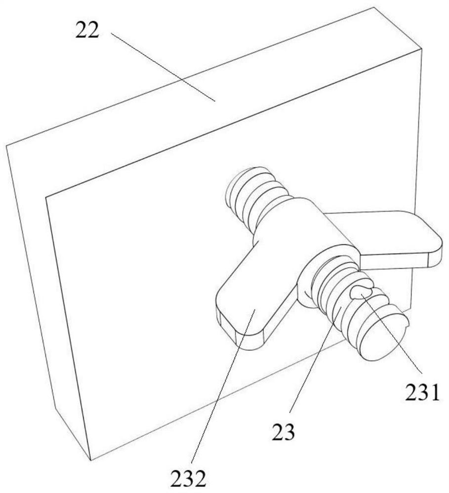
[0045] see Figure 1 to Figure 3 , this embodiment provides a discharge device, including a discharge conductor 1, a grounding device 2 and an insulating rod 3, the discharge conductor 1 includes a fixed frame 11, an elastic connection assembly 12 and two discharge parts, and the elastic connection assembly 12 is arranged on the fixed frame In the middle of 11, one discharge part is elastically clamped between one end of the fixed frame 11 and the elastic connection component 12, and the other discharge part is elastically clamped between the other end of the fixed frame 11 and the elastic connection component 12. On the fixed frame 11 With the cooperation of the elastic connection assembly 12, the two discharge parts can move relative to the fixed frame 11, and are used to discharge the two terminals of the capacitor; the grounding device 2 is connected to the discharge conductor 1 through the ground wire 21, and is used to connect to the discharge conductor 1 forms a dischar...

Embodiment 2

[0079] This embodiment discloses a discharge device whose structure is basically the same as that of the first embodiment, including a discharge conductor 1 , a grounding device 2 and an insulating rod 3 .

[0080] see Figure 4 to Figure 6 The difference between this embodiment and Embodiment 1 is that the insulating rod 3 is formed by connecting a plurality of support tubes 31 in the axial direction, one end of the insulating rod 3 is the operating end, and the other end is the working end, and the working end is movably connected to the The discharge conductor 1 realizes the connection between the insulating rod 3 and the discharge conductor 1 at any angle, which is convenient for maintenance personnel to flexibly adjust the position between the discharge conductor 1 and the insulating rod 3 according to the actual discharge operation conditions, and meets various discharge operation requirements.

[0081] Optionally, the insulating rod 3 is formed by connecting two support...


PUM


Abstract

The invention relates to the field of electrical auxiliary equipment, in particular to a discharge device, which includes a discharge conductor, a grounding device and an insulating rod. The discharge conductor includes a fixed frame, an elastic connection component and two discharge parts. The elastic connection component is arranged in the middle of the fixed frame. The discharge part is elastically clamped between one end of the fixed frame and the elastic connection component, and the other discharge part is elastically clamped between the other end of the fixed frame and the elastic connection component. The discharge part can move relative to the fixed frame and is used for the capacitor. The two terminals discharge; the grounding device is electrically connected to the discharge conductor; the insulating rod is movably connected to the discharge conductor. Discharge the two terminals of the capacitor at the same time through the two discharge parts; with the cooperation of the fixed frame and the elastic connection component, the discharge part can move relative to the fixed frame under a small external force, which not only ensures that the discharge part is fully in contact with the capacitor terminals, It can also adjust the position of the discharge part to adapt to the capacitor, reduce the effort and workload of the maintenance personnel, and improve the discharge efficiency.

Description

technical field [0001] The invention relates to the field of electrical auxiliary equipment, in particular to a discharge device. Background technique [0002] Shunt capacitors are used in the power system to compensate the reactive power of the inductive load of the power system to improve the power factor and voltage quality, thereby reducing line loss, increasing the output power of the system or transformer, and achieving the purpose of stable system operation. When the capacitor is disconnected and the circuit breaker is disconnected from the power grid, although it has been discharged through its own discharge coil, the capacitor still has residual charge. When the maintenance personnel touch the capacitor, the residual charge will cause the maintenance personnel to get an electric shock. Therefore, in order to ensure the safety of personnel during capacitor maintenance operations, parallel capacitors should be discharged multiple times one by one before maintenance. ...

Claims


Application Information

Patent Timeline
Patent Type & Authority Patents(China)
IPC IPC(8): H02B3/00
CPCH02B3/00
Inventor 龚演平张斌斌傅龙伟汪东曾小忠陈正龙陈慧聪张焕燊鄢雨候刘晓洲李佳奇卢紫薇温云
Owner GUANGDONG POWER GRID CO LTD
Why Eureka
Try Eureka