Soft hydraulic micro-scissors

A scissors, hydraulic technology, applied in the fields of surgical scissors, medical science, surgery, etc., can solve the problem of inability to pass through the curved working channel, and achieve the effect of reducing the risk of iatrogenic injury, reducing the difficulty of operation, and simple operation.

Active Publication Date: 2019-06-28
兴化市人民医院 +2
View PDF6 Cites 0 Cited by
  • Summary
  • Abstract
  • Description
  • Claims
  • Application Information

AI Technical Summary

Problems solved by technology

[0004] Purpose of the invention: Aiming at the defects of repeated replacement of surgical instruments during endoscopic neurosurgery and the inability to pass through the curved working channel in the prior art, the present invention provides a minimally invasive soft hydraulic micro scissors

Method used


Image

  • Soft hydraulic micro-scissors
  • Soft hydraulic micro-scissors
  • Soft hydraulic micro-scissors

Examples


Embodiment 1

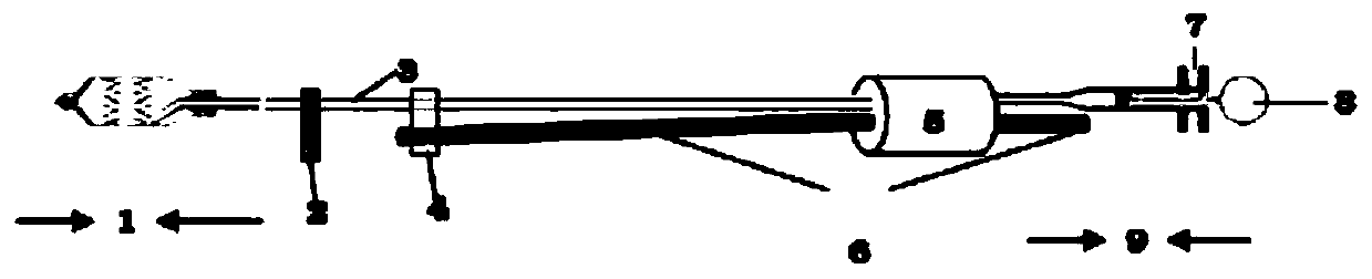
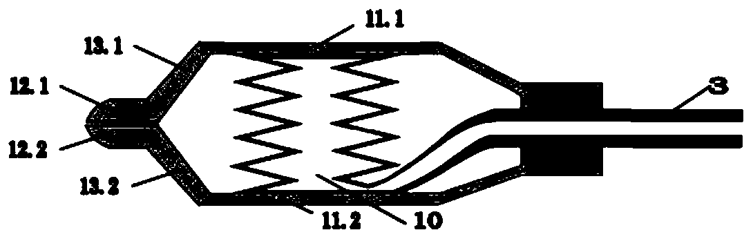
[0030] like figure 1 , figure 2 , image 3 As shown, the hydraulic micro-scissors of the present invention include a micro-scissors head 1, a water pipe rod fixed wing 2, a water pipe rod 3, an endoscope position bracket 4, a micro-scissors straight plug 5, a soft / hard fiber endoscope 6 and a manual hydraulic pressure Accessories9. Wherein, the micro-scissor head 1 includes a hydraulic water bladder 10, an upper blade 12.1, a lower blade 12.2, an upper scissor arm 11.1, a lower scissor arm 11.2, a transition part 13.1 between the upper scissor arm and the upper blade, and a transition between the lower scissor arm and the lower blade. Section 13.2. The water pipe rod 3 and the soft / hard fiber endoscope 6 all pass through the corresponding apertures of the straight plug 5 .

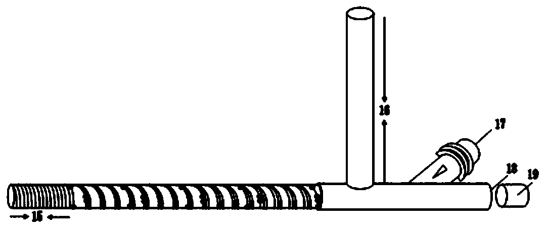
[0031] like figure 2 As shown, in the present embodiment, the hydraulic micro-scissors of the present invention are inserted into the steering soft suction device through the straight pipe 18 of the...

Embodiment 2

[0044] When operating under a neurosurgery microscope, the present invention can be removed figure 1 The water pipe rod fixed wing 2 and the endoscope position support 4, the micro-scissors straight plug 5 and the software / hard fiber endoscope 6 parts in the micro-scissors head are stretched into the operating field under the aid of the microscope field of view. The corresponding position is used to cut the target tissue. Open the upper and lower scissor arms of the head of the micro-scissors, observe the cutting effect, and repeat the above steps until the target tissue is severed.

[0045] The turning soft suction device in the above two embodiments can pass through a straight channel or an arc channel guide. When the turning soft suction device passes through the arc guide, the fiber endoscope adopts a soft fiber endoscope; When passing through the straight channel introducer, the fiber endoscope can be soft or rigid fiber endoscope.


PUM


Abstract

The invention discloses a soft hydraulic micro-scissors, which comprises a micro-scissors head with a water bag, a water pipe rod, a hydraulic fitting and a micro-scissors straight plug, wherein the micro-scissors head is connected with the hydraulic fitting through the water pipe rod, and the hydraulic fitting controls the opening and closing of the micro-scissors head by controlling directionaltelescoping of the water bag. After being combined with a fiber endoscope, the micro scissors and the fiber endoscope are placed into a steering soft suction device with negative pressure, the suctiondevice is placed into a guide device, the direction of the micro- scissors head is controlled by the suction device, and the hydraulic fitting controls the opening and closing of the head part of themicro-scissors by controlling directional telescoping of the water bag, and then the shear is carried out under the negative pressure. By means of the device, controlled by a minimally invasive steering suction device, the negative pressure suction and endoscope assistance are utilized, iatrogenic injury of nerves, blood vessels, brain tissues and the like is avoided, complications of nerve andblood vessel injury in a perioperative period are obviously reduced, meanwhile, in an operation, uncoordinated operation of two persons is avoided, the operation efficiency is improved, and the operation cost is reduced.

Description

technical field [0001] The invention relates to scissors in medical instruments in minimally invasive neurosurgery, in particular to a soft hydraulic micro-scissor. Background technique [0002] In neurosurgery, tissues such as arachnoid, tumor capsule, and blood vessels need to be cut, especially in endoscopic neurosurgery, where deep brain tissue is involved, the space is narrow, and the channel is long and narrow. Traditional micro scissors are difficult to operate. , the movement space required behind the scissors cross is large. In the curved working channel, traditional scissors or micro scissors cannot work effectively at all. This puts forward new requirements for the scissors in the arc working channel surgery of neurosurgery. [0003] Secondly, doctors in neurosurgery and other departments have found the following shortcomings in the existing micro-scissors in the long-term operation experience: (1) The gun-like arms of scissors or micro-scissors are getting long...

Claims


Application Information

Patent Timeline
Patent Type & Authority Applications(China)
IPC IPC(8): A61B17/3201A61B17/00
Inventor 李宽正陈陆馗
Owner 兴化市人民医院
Why Eureka
Try Eureka