
Power transmission tower-oriented cable erecting device with joint protection function

A protection function, transmission tower technology, applied in overhead lines/cable equipment, devices for relieving mechanical tension, etc., can solve problems such as safety accidents, increased stress on cable connections, and wear, etc., to protect birds and reduce load. force and avoid safety accidents

Inactive Publication Date: 2021-07-16
南京亚焱源电子商务有限公司
View PDF0 Cites 0 Cited by
  • Summary
  • Abstract
  • Description
  • Claims
  • Application Information

AI Technical Summary

Problems solved by technology

[0003] However, when the existing iron tower cable erection device is in use, the cable will swing slightly with the wind when encountering strong winds, and birds will often stay on the cable on the cable erected in the wild, which will cause damage to the cable connection. Increased force will easily cause wear and tear and leakage and lead to safety accidents. Therefore, those skilled in the art provide a cable erection device for transmission towers with a connection protection function to solve the problems raised in the above-mentioned background technology

Method used


Image

  • Power transmission tower-oriented cable erecting device with joint protection function
  • Power transmission tower-oriented cable erecting device with joint protection function
  • Power transmission tower-oriented cable erecting device with joint protection function

Examples


Embodiment Construction

[0023] The following will clearly and completely describe the technical solutions in the embodiments of the present invention with reference to the accompanying drawings in the embodiments of the present invention. Obviously, the described embodiments are only some, not all, embodiments of the present invention. Based on the embodiments of the present invention, all other embodiments obtained by persons of ordinary skill in the art without making creative efforts belong to the protection scope of the present invention.

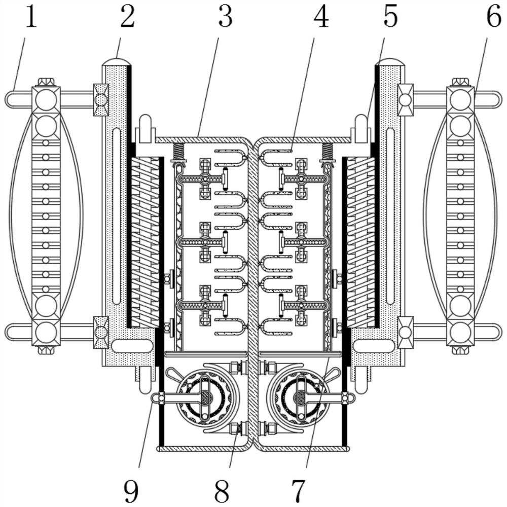
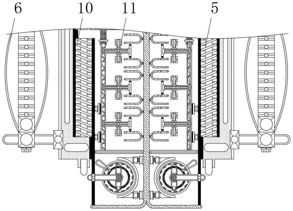
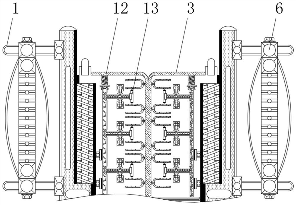
[0024] see Figure 1-5 , a cable erection device for a transmission tower with a connection protection function, comprising a housing 3, the outer surface of the housing 3 is fixedly connected to a limiting column 5, and the outer surface of the limiting column 5 is surrounded by a fastening spring 10, fastened One end of the spring 10 is fixedly connected with the outer surface of the limiting post 5, the other end of the fastening spring 10 is fixedly connec...


PUM


Abstract

The invention belongs to the technical field of power equipment and relates to a power transmission tower-oriented cable erecting device with a joint protection function. The device comprises a shell, a limiting column is fixedly connected to the outer surface of the shell, a limiting plate is slidably connected to the outer surface of the limiting column, a fixing column is fixedly connected to the outer surface of the limiting plate, the outer surface of the fixing column is movably connected with a fastening strip, and the interior of the shell is fixedly connected with a mounting seat; when the limiting plate slides on the outer surface of the limiting column, part of acting force borne by an electric wire is transferred to the limiting plate and the limiting column, and when the limiting plate and the limiting column slide relative to each other, the transferred force is offset under the action of a fastening spring between the limiting plate and the limiting column, so that the acting force can act on the electric wire as little as possible, and therefore, the outer surface of the joint between the electric wire and the shell is prevented from being abraded more seriously when the wire shakes, and the situation of safety accidents caused by electric leakage is avoided.

Description

technical field [0001] The invention relates to the technical field of electric power equipment, in particular to a cable erection device for a power transmission tower with a connection point protection function. Background technique [0002] The transmission tower is the supporting point of the overhead line. The transmission tower is used to erect the line to connect the power to thousands of households. The transmission tower is to fix the cable on the transmission tower through the cable erection device, and the cable can be flexibly moved through the erection device It is fixed on the transmission tower, which is convenient for the erection work of the electric staff and improves the erection work efficiency of the staff. [0003] However, when the existing iron tower cable erection device is in use, the cable will swing slightly with the wind when encountering strong winds, and birds will often stay on the cable on the cable erected in the wild, which will cause damag...

Claims


Application Information

Patent Timeline
IPC IPC(8): H02G1/04H02G7/04
CPCH02G1/04H02G7/04
Inventor 袁亚焱
Owner 南京亚焱源电子商务有限公司
Learn More