
Self-driven sun tracking system

A sun-tracking and self-driving technology, applied in the field of solar energy, can solve the problems of structural complexity, low utilization rate, and difficult installation, and achieve the effect of solving complex structures

Inactive Publication Date: 2021-07-16
恩拓必(临沂)能源发展有限责任公司
View PDF7 Cites 2 Cited by
  • Summary
  • Abstract
  • Description
  • Claims
  • Application Information

AI Technical Summary

Problems solved by technology

In addition, the disadvantages of these trackers are the complexity of the structure and the need for coordination of positioning specifications, maintenance, platforms, external online data requirements, additional equipment, etc.
As a result, installation is difficult for the average consumer, making trackers almost unmarketable to individuals and below-average usage

Method used


Image

  • Self-driven sun tracking system
  • Self-driven sun tracking system
  • Self-driven sun tracking system

Examples


Embodiment 1

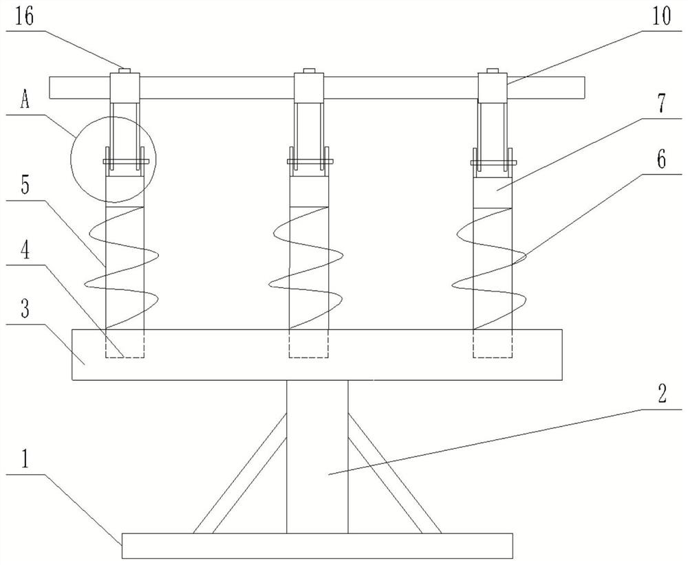
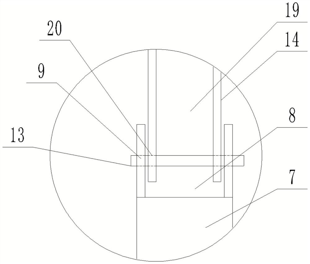
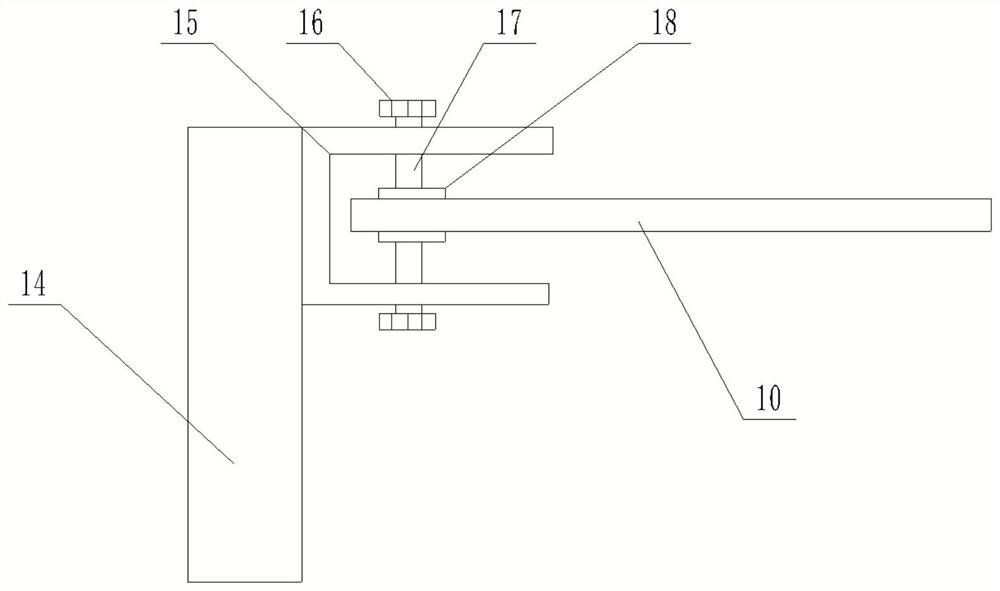
[0026] refer to Figure 1-5 , the present invention provides a self-driven sun tracking system, comprising a base 1, one end of a column 2 is fixedly connected to the base 1, and a tray 3 is fixedly connected to the other end of the column 2, and the column 2 is the same as the tray. The support makes the tray 3 more convenient to use. The top of the tray 3 is provided with a number of telescopic mechanisms. Alloy spring, and adopt Ni-Ti or Cu-Al-Be alloy to make, the first spring 6 has good heat absorption capacity, can fully absorb solar radiation energy, the bottom of described first spring 6 is fixed on the described The top of the tray 3, the top of the first spring 6 is affixed to the top of the telescopic rod 5. When the sun radiates to the first spring 6, the first spring 6 close to the sun absorbs the solar radiation energy, and the temperature rises accordingly. High, so that the first spring 6 close to the sun is compressed and deformed, and the telescopic rod 5 is...

Embodiment 2

[0039] On the basis of embodiment 1, with reference to Image 6 , the bottom of the tray 3 is fixedly connected with a number of fixed frames 22, the fixed frame 22 is provided with a motor 23, the motor 23 is placed corresponding to the position of the clamp block 15, and the output shaft of the motor 23 is fixedly connected with a wire Rod 24, the screw 24 is covered with a turntable 25, the top of the turntable 25 is fixed with a support tube 26, the support tube 26 is provided with a through hole, and the top end of the support tube 26 is sleeved on the outside of the bearing 27 , the first connection block 7 is sleeved on the inner side of the bearing 27, the bottom end of the screw 24 is provided with a protrusion 28, the top of the telescopic rod 5 is symmetrically provided with a limit block 29 on both sides, and the support tube 26 The diameter is smaller than the distance between the two limit blocks 29, and the bottom of the telescopic rod 5 is symmetrically provide...


PUM


Abstract

A self-driven sun tracking system disclosed by the invention comprises a base. A stand column is fixedly connected to the base, a tray is fixedly connected to the stand column, a plurality of telescoping mechanisms are arranged at the top of the tray, each telescoping mechanism comprises a telescoping rod, a first spring is arranged in the telescoping rod, the bottom of the first spring is fixedly connected to the top of the tray, and the top of the first spring is fixedly connected to the top of the telescoping rod. The first spring can be compressed and stretched along with the intensity of illumination and drive the telescopic rod to move, a movable mechanism is further hinged to the top end of the telescopic rod, the angle of the solar panel can be changed along with movement of the sun, the solar panel faces the sun all the time, and therefore automatic sun tracking is achieved.The top of the movable mechanism is fixedly connected with a clamping mechanism; and the clamping mechanism is detachably connected with a solar panel, the tray is provided with a storage battery and a controller, the storage battery is electrically connected with the controller, and the self-driven sun tracking system solves the problems that an existing mechanical sun tracker is complex in structure and consumes extra power.

Description

technical field [0001] The invention relates to the technical field of solar energy, in particular to a self-driven sun tracking system. Background technique [0002] At present, the solar panels of solar power generation systems for communication equipment are all fixed installations, and their inclination angles and azimuth angles are fixed and will not change. Due to the earth's rotation and revolution around the sun, the sun's daily hour angle and seasonal declination angle change. Then the incident angle of solar light on the fixedly installed solar panels changes momentarily. Under the same solar radiation intensity, the amount of energy collected per unit area of ​​the solar panel is different because of the different incident angles of sunlight. When the sun's rays are vertically projected onto the solar panel (incident angle θ=0°), the solar radiation energy received by the solar panel is maximum; and when the solar light is not vertically projected on the solar p...

Claims


Application Information

Patent Timeline
IPC IPC(8): H02S20/32H02S30/00F24S30/00F24S30/425
CPCF24S30/00F24S30/425H02S30/00H02S20/32Y02E10/47Y02E10/50
Inventor 肖松刘艳娜
Owner 恩拓必(临沂)能源发展有限责任公司
Learn More