
Steam turbine rotor descaling box and descaling method thereof

A technology for steam turbine rotors and casings, which is applied to separation methods, chemical instruments and methods, cleaning methods and utensils, etc., can solve the problems of inconvenient cleaning and descaling of steam turbine rotors, waste of labor time, and inconvenient operation. Facilitate cleaning and descaling operations, improve the efficiency of cleaning and descaling, and improve the effect of convenience

Active Publication Date: 2021-07-20
HANGZHOU STEAM TURBINE CASTING & FORGING
View PDF7 Cites 0 Cited by
  • Summary
  • Abstract
  • Description
  • Claims
  • Application Information

AI Technical Summary

Problems solved by technology

[0003] 1. When descaling the steam turbine rotor descaling box in the prior art, due to the heavy weight of the steam turbine rotor, it is difficult to place the steam turbine rotor inside the descaling box, and the operation is very inconvenient;
[0004] 2. The steam turbine rotor descaling box in the prior art can usually only place the steam turbine rotor to be cleaned and descaled on the surface of the descaling box. Since the steam turbine rotor to be cleaned and descaled cannot be rotated, the steam turbine The cleaning and descaling of the rotor is inconvenient and the efficiency of cleaning and descaling is relatively low;
[0005] 3. When descaling the steam turbine rotor descaling box in the prior art, most of the hand-held high-pressure spray guns are aimed at the surface of the steam turbine rotor to clean and descale the steam turbine, which leads to a waste of a lot of manual work time;
[0006] 4. The steam turbine rotor descaling box in the prior art cannot filter and recycle the cleaning liquid during descaling, resulting in a large waste of cleaning liquid, and the cost of cleaning and descaling the steam turbine rotor is relatively high. Therefore, we propose a A kind of steam turbine rotor descaling box and its descaling method are used to solve the above problems

Method used


Image

  • Steam turbine rotor descaling box and descaling method thereof
  • Steam turbine rotor descaling box and descaling method thereof
  • Steam turbine rotor descaling box and descaling method thereof

Examples


Embodiment approach

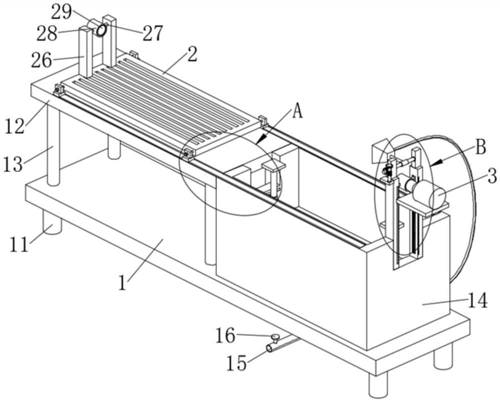
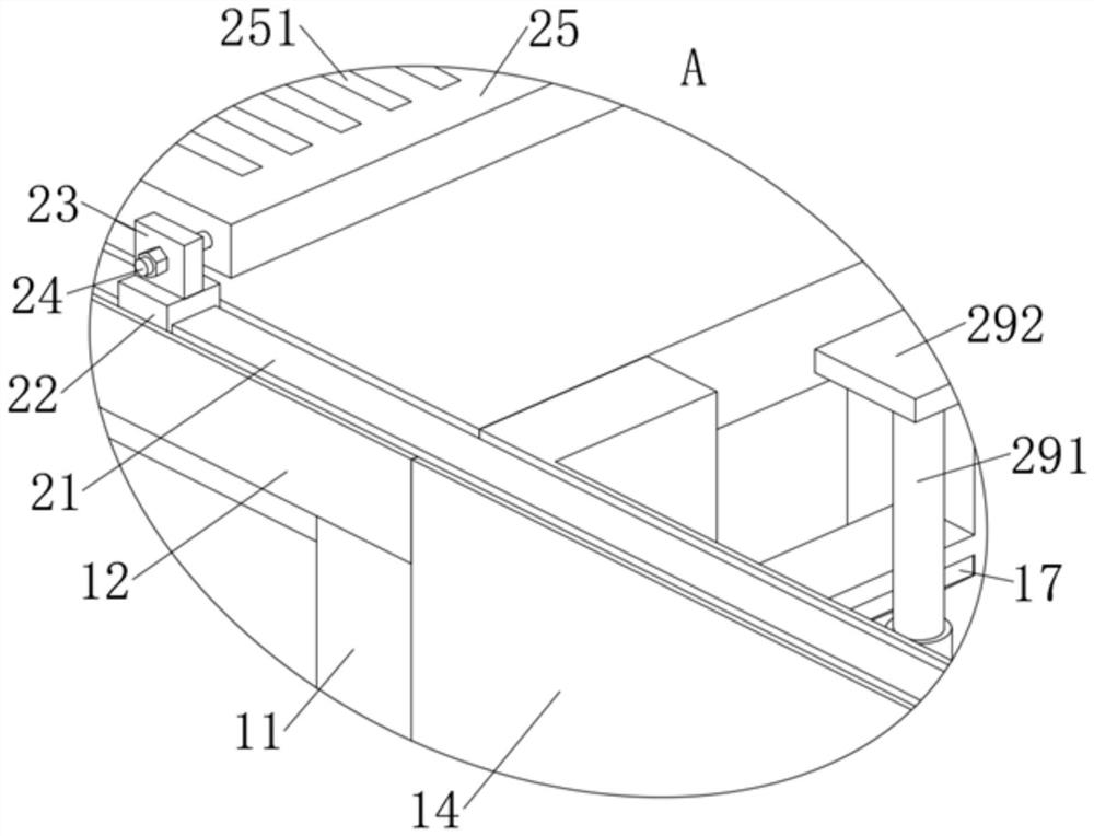
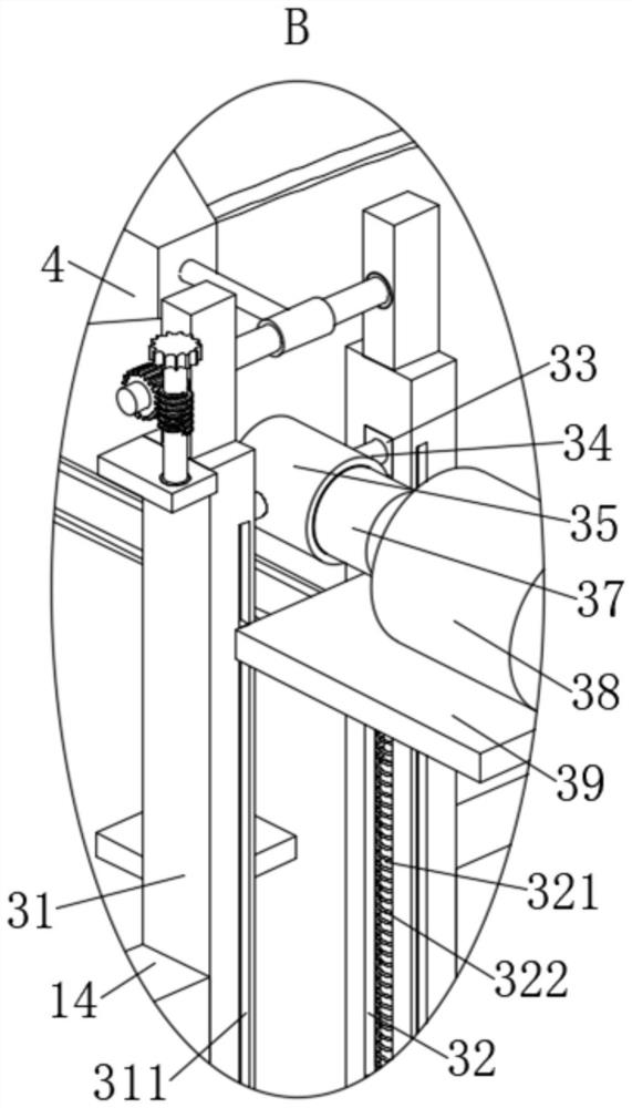
[0042] As an embodiment of the present invention, the pushing mechanism 2 includes a linear electric cylinder 21, the linear electric cylinder 21 is fixedly connected to the console 12, the linear electric cylinder 21 is fixedly connected to the descaling box 14, and the two sets of linear electric cylinders 21 The surface is symmetrically slidably connected with a slider 22. By opening the linear electric cylinder 21, the linear electric cylinder 21 can drive the slider 22 to move horizontally. The upper surface of the slider 22 is fixedly installed with a first fixed plate 23. One side threaded rotation is connected with fastening bolt 24, and between fastening bolt 24, thread clip is connected with moving plate 25, and through knob fastening bolt 24, can realize the fixation and separation of moving plate 25 and fastening bolt 24 conveniently, The upper surface of the moving plate 25 is symmetrically fixed with the first vertical plate 26, and the moving plate 25 can drive t...


PUM


Abstract

The invention discloses a steam turbine rotor descaling box. The box comprises a bottom plate, an operation table is fixedly arranged on the upper surface of the bottom plate, a descaling box body is fixedly installed on the upper surface of the bottom plate, the operation table is fixedly connected with the descaling box body, and a fixing frame is fixedly installed on the inner wall of the descaling box body; and a pushing mechanism is fixedly mounted on the upper surface of the operation table. Compared with the prior art, the box has the advantages that cleaning liquid sprayed out when a high-pressure spray gun body works falls on the upper surface of a steam turbine rotor and flows into the descaling box body, dirt in the cleaning liquid is filtered through a filter plate, the clean cleaning liquid flows to the lower surface of the filter plate through filter holes in the surface of the filter plate, and then the clean cleaning liquid is conveyed into the high-pressure spray gun body through a water pump, so that filtering of the cleaning liquid and recycling of the filtered cleaning liquid are conveniently completed, therefore, the cleaning liquid required in the cleaning and descaling process is saved, and the cost for cleaning and descaling the steam turbine rotor is reduced.

Description

technical field [0001] The invention relates to the technical field of steam turbine rotor descaling, in particular to a steam turbine rotor descaling box and a descaling method thereof. Background technique [0002] Steam turbine rotor: a combination of steam turbine rotating parts such as the main shaft, impeller or drum, moving blades and couplings. It is the main equipment of modern thermal power plants and is also used in metallurgical industry, chemical industry, and ship power plant. The steam turbine rotor descaling box in the prior art has the following problems during descaling: [0003] 1. When descaling the steam turbine rotor descaling box in the prior art, due to the heavy weight of the steam turbine rotor, it is difficult to place the steam turbine rotor inside the descaling box, and the operation is very inconvenient; [0004] 2. The steam turbine rotor descaling box in the prior art can usually only place the steam turbine rotor to be cleaned and descaled o...

Claims


Application Information

Patent Timeline
IPC IPC(8): B08B3/02B08B13/00B01D29/03
CPCB08B3/02B08B13/00B01D29/03Y02E10/20
Inventor 周黎明唐庆伟
Owner HANGZHOU STEAM TURBINE CASTING & FORGING
Learn More