
Industrial flue gas exhaust cleaning tower

A technology of industrial flue gas and washing tower, which is applied in the direction of using liquid separation agent, combination device, separation device, etc., which can solve the problem of corrosion crystallization and agglomeration, poor effect of water mist collector on collecting condensed dust particles and water droplets, and pollution Factory environment and other issues

Inactive Publication Date: 2020-10-30
PINGXIANG HUAXING ENVIRONMENTAL PROTECTION ENG TECH CO LTD
View PDF6 Cites 0 Cited by
  • Summary
  • Abstract
  • Description
  • Claims
  • Application Information

AI Technical Summary

Problems solved by technology

In this method, the coal gas stays in the exhaust purification tower for a short time, so it is not ideal to make the gas fully contact with the atomized water, and the water mist collector is not effective in collecting the water droplets of condensed dust particles, which leads to the drying of ammonium sulfate. The recovery rate of tail gas is low, the acid mist exceeds the standard, and a large amount of water droplets of ammonium sulfate dust or condensed dust particles are discharged into the environment, polluting the environment of the factory area
Moreover, when the dry tail gas does not reach the saturated humidity, the evaporation of water will easily lead to crystallization and sticking to the wall in the later stage, causing problems such as aerosol, secondary pollution of smog, excessive acid mist, droplet entrainment, and corrosion crystallization agglomeration.

Method used


Image

  • Industrial flue gas exhaust cleaning tower
  • Industrial flue gas exhaust cleaning tower
  • Industrial flue gas exhaust cleaning tower

Examples


Embodiment Construction

[0025] For a better understanding of the application, various aspects of the application will be described in more detail with reference to the accompanying drawings. It should be understood that these detailed descriptions are descriptions of exemplary embodiments of the application only, and are not intended to limit the scope of the application in any way. Throughout the specification, the same reference numerals refer to the same elements.

[0026] In the drawings, the thickness, size and shape of objects have been slightly exaggerated for convenience of illustration. The drawings are merely examples and are not strictly drawn to scale.

[0027] It should also be understood that the terms "comprising", "comprising", "having", "comprising", "comprising", when used in this specification, mean that there are described features, integers, steps, operations, elements and / or or components, but does not exclude the presence or addition of one or more other features, integers, s...


PUM


Abstract

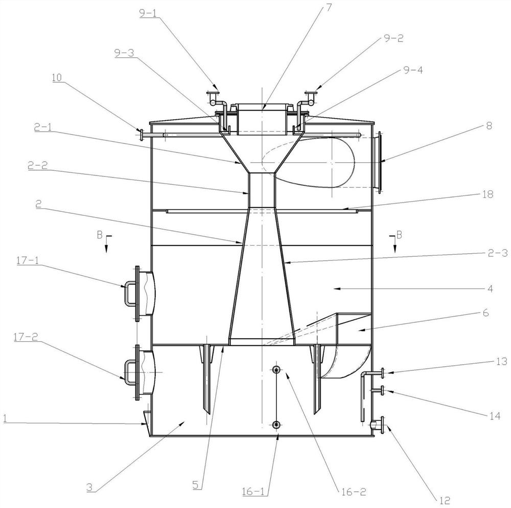
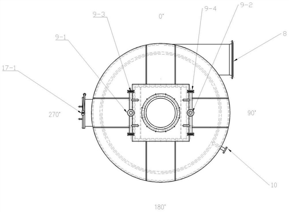
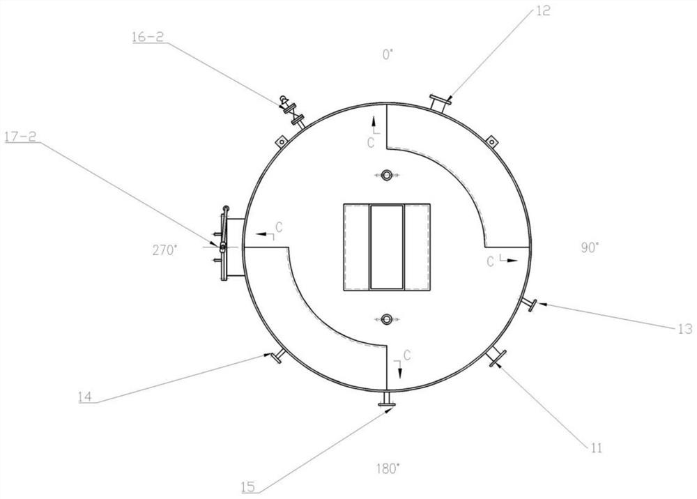
The invention relates to the field of tail gas purification technical equipment for coking production, and provides an industrial flue gas exhaust cleaning tower. Five purification guarantees are arranged, specially comprising a shell, the interior of the shell is divided into an inner cylinder, a liquid storage chamber and a spraying area. An air inlet communicated with the outside is formed in the upper part of the inner cylinder; the liquid storage chamber is communicated with the lower part of the inner cylinder; an annular partition plate is arranged between the liquid storage chamber andthe side wall of the inner cylinder. The spraying area is defined by an annular partition plate, the side wall of the inner barrel, the inner wall of the shell and the inner top face of the shell together. Two convolute air passages are further arranged between the liquid storage chamber and the inner wall of the shell; a circulating liquid injection pipe is arranged outside the side wall of theair inlet; a spray washing liquid pipe is arranged at the top of the spray area, a plurality of spray holes are formed in the pipe wall of the spray washing liquid pipe, an air outlet pipe is arrangedat the position, below the spray washing liquid pipe, of the side wall of the shell, a mist catcher is arranged below the air outlet pipe, and an injection port and an emptying port which are communicated with the liquid storage chamber are further sequentially formed in the side wall of the shell from top to bottom.

Description

technical field [0001] The invention relates to the technical equipment field of tail gas purification in coking production, and more specifically relates to an industrial flue gas exhaust cleaning tower. Background technique [0002] In the coking industry, in order to recover the ammonia in the gas, the saturator method is usually used to produce ammonium sulfate. The tail gas produced after the ammonium sulfate is dried will first enter the dust collector for dust removal treatment, and after the ammonium sulfate dust in the tail gas is removed, it will be discharged into the atmosphere. . With the intensification of production and the lack of capacity of the dust collector itself, a large amount of ammonium sulfate dust is often entrained in the tail gas and enters the atmosphere, polluting the environment. Due to the high cost of production equipment and pipeline transformation, the solution to ammonium sulfate tail gas dust pollution is usually to transport the tail g...

Claims


Application Information

Patent Timeline
Patent Type & Authority Applications(China)
IPC IPC(8): B01D47/06B01D47/00B01D50/00
CPCB01D47/06B01D47/00B01D50/00B01D2247/10B01D50/40
Inventor 李波李婵李凯侯建国李斌宋亚波李幸
Owner PINGXIANG HUAXING ENVIRONMENTAL PROTECTION ENG TECH CO LTD
Learn More