
Riveting mechanism with pressure and displacement monitoring function

A displacement monitoring and riveting pressure technology, applied in the direction of measuring devices, instruments, etc., can solve problems such as unable to adjust or repair, unable to be found in time, unable to detect the movement of riveting pressure components, etc., to prevent offset or shaking, The effect of facilitating repair and replacement and reducing the difficulty of parts replacement

Pending Publication Date: 2021-07-20
儒拉玛特自动化技术(合肥)有限公司
View PDF8 Cites 1 Cited by
  • Summary
  • Abstract
  • Description
  • Claims
  • Application Information

AI Technical Summary

Problems solved by technology

[0002] At present, when the existing riveting device is in use, since the riveting component is directly driven by the private electric cylinder, and the movement of the riveting component cannot be detected, if the riveting component is in use, if it is shifted or tilted, it cannot be corrected in time. Therefore, only when the riveting component is obviously damaged, it can be found in time. At this time, it cannot be adjusted through adjustment or repair. Therefore, we propose a riveting with pressure and displacement monitoring. mechanism

Method used


Image

  • Riveting mechanism with pressure and displacement monitoring function
  • Riveting mechanism with pressure and displacement monitoring function
  • Riveting mechanism with pressure and displacement monitoring function

Examples


Embodiment Construction

[0034] In order to make the technical means, creative features, goals and effects achieved by the present invention easy to understand, the present invention will be further described below in conjunction with specific embodiments.

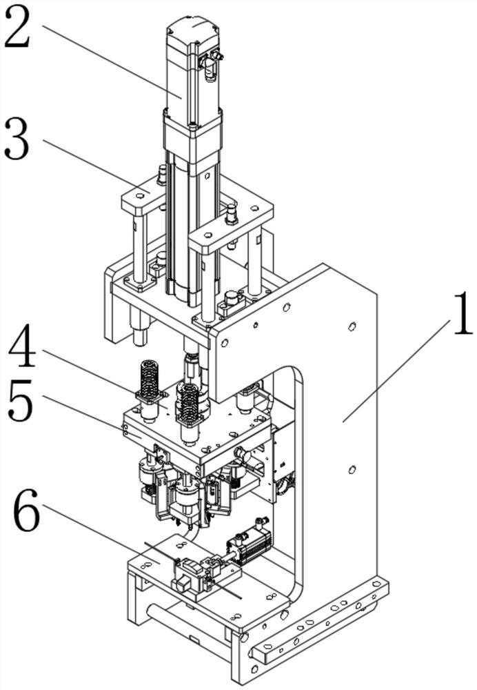
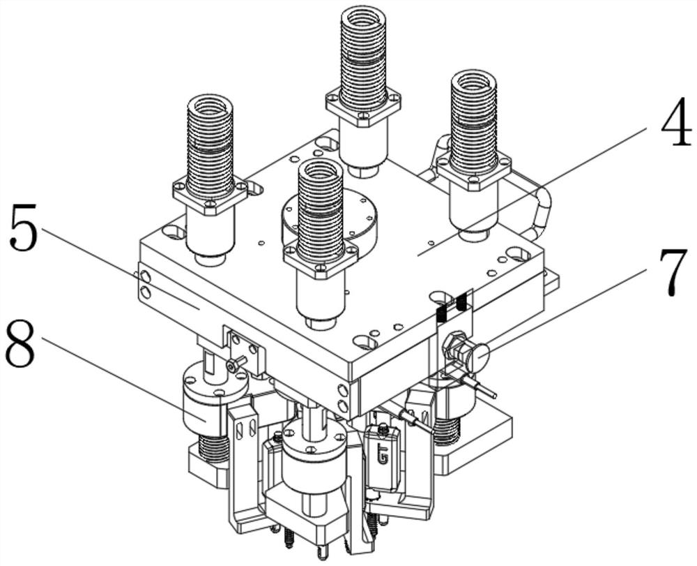
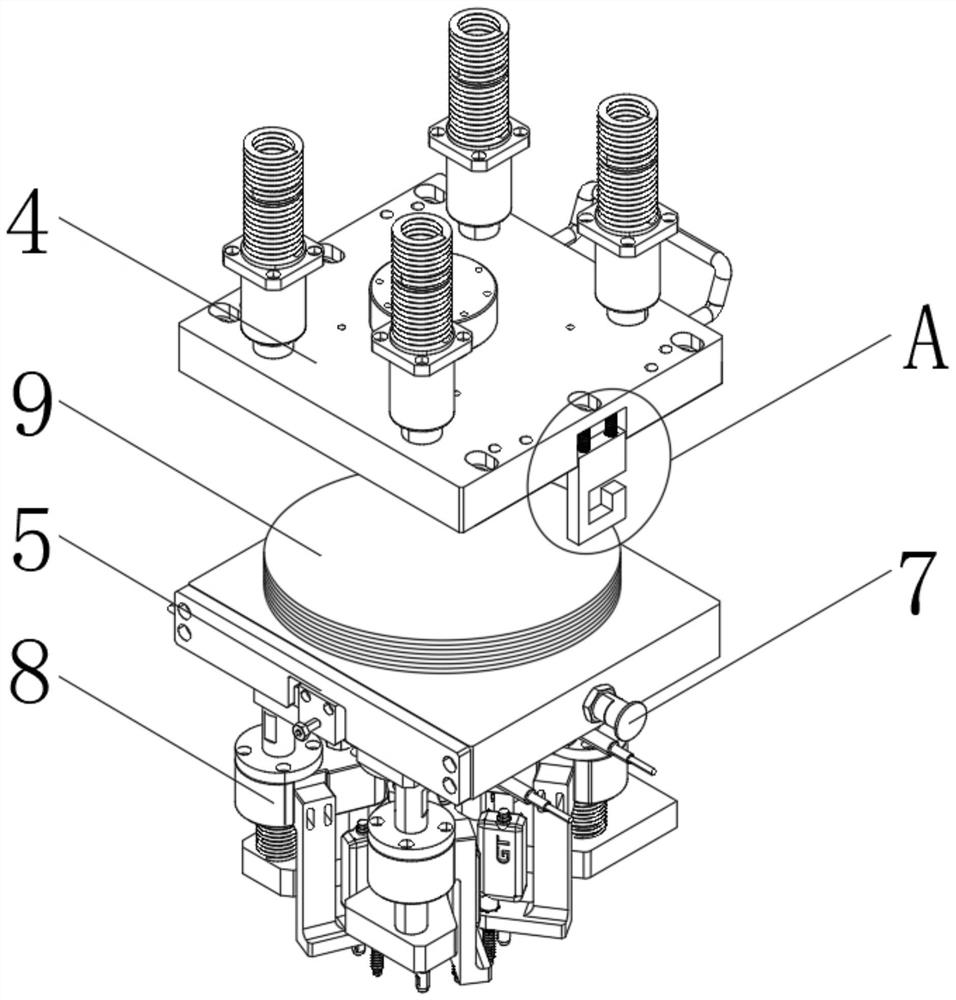
[0035] refer to Figure 1-4 As shown, a riveting mechanism with pressure and displacement monitoring includes a support frame 1, the top of the support frame 1 is connected with a private electric cylinder 2, and a limit position for protecting the private electric cylinder 2 is installed on the top of the support frame 1 platform 3, and the telescopic end of the electric cylinder 2 is connected with a linkage plate 4, the base 6 installed at the bottom of the support frame 1 corresponds to the installation plate 5 installed at the bottom of the linkage plate 4, wherein,

[0036] The top center of the mounting plate 5 is provided with a disc-shaped docking plate 9, and the bottom of the linkage plate 4 is provided with a docking groove that is thr...


PUM


Abstract

The invention discloses a riveting mechanism with a pressure and displacement monitoring function. A butt joint disc is arranged at the center of the top of an installing plate; a butt joint groove in threaded connection with the butt joint disc is formed in the bottom of a linkage plate; the two sides of the linkage plate are connected to limiting buckles through springs; and limiting pins corresponding to the limiting buckles up and down are installed at the two sides of the installing plate. According to the riveting mechanism with the pressure and displacement monitoring function, firstly, the butt joint disc is arranged at the top of the installing plate, and the limiting buckles are arranged at the two sides of the linkage plate, so that riveting components can be replaced conveniently, and meanwhile, the installation difficulty of the riveting components can be lowered; secondly, a pressure sensor is arranged between the installing plate and a connecting piece, so that not only can the pressure of each riveting component be detected, but also whether the pressure distribution of the device is uniform or not can be detected; and thirdly, a riveting needle is arranged at the bottom of the connecting piece, whether the riveting needle moves in place or not can be detected, and meanwhile, whether a rivet inclines or not can be detected.

Description

technical field [0001] The invention relates to the technical field of riveting, in particular to a riveting mechanism with pressure and displacement monitoring. Background technique [0002] At present, when the existing riveting device is in use, since the riveting component is directly driven by the private electric cylinder, and the movement of the riveting component cannot be detected, if the riveting component is in use, if it is shifted or tilted, it cannot be corrected in time. Therefore, only when the riveting component is obviously damaged, it can be found in time. At this time, it cannot be adjusted through adjustment or repair. Therefore, we propose a riveting with pressure and displacement monitoring. mechanism. Contents of the invention [0003] The main purpose of the present invention is to provide a riveting mechanism with pressure and displacement monitoring, which can effectively solve the problems in the background technology. [0004] In order to ach...

Claims


Application Information

Patent Timeline
Patent Type & Authority Applications(China)
IPC IPC(8): B21J15/10B21J15/38G01D21/02
CPCB21J15/10B21J15/38G01D21/02
Inventor 刘小威
Owner 儒拉玛特自动化技术(合肥)有限公司
Learn More