Device for handling printing plate on printing press

A printing plate and printing machine technology, applied to printing machines, general parts of printing machinery, printing, etc., to achieve the effect of saving assembly and adjustment time

Pending Publication Date: 2021-07-20
HEIDELBERGER DRUCKMASCHINEN AG
View PDF1 Cites 0 Cited by
  • Summary
  • Abstract
  • Description
  • Claims
  • Application Information

AI Technical Summary

Problems solved by technology

This prior art equipment is not well suited for automation

Method used


Image

  • Device for handling printing plate on printing press
  • Device for handling printing plate on printing press

Examples


Embodiment Construction

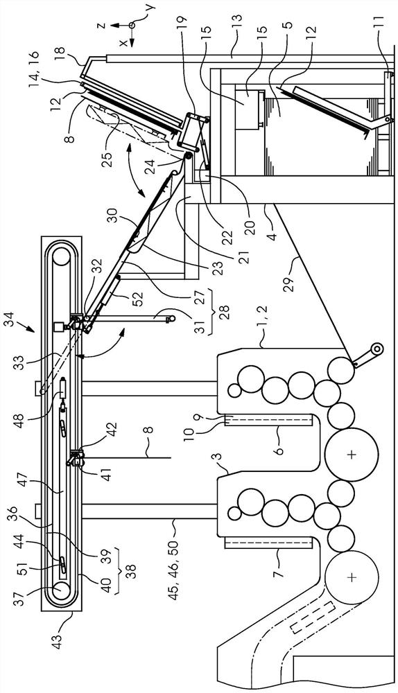
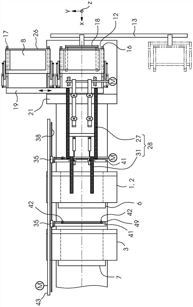
[0019] The printing press 1 comprises printing units 2 , 3 arranged in a row for offset printing on sheets which form a stack 5 in a feeder 4 . Each printing unit 2, 3 is equipped with a plate changer 6, 7 for a printing plate 8, which has a shaft 9 for a new printing plate 8 (so-called new printing plate) and a A shaft 10 for used printing plates 8 (so-called old printing plates). The printing press 1 is combined with a printing plate logistics system which conveys these printing plates 8 to the plate changers 6 , 7 and back again after they have been used. An operator removes the pallet 12 with the printing plates 8 therein from the ground transport device 11 and delivers the pallet 12 to the pallet lifting device 13 .

[0020] The orthogonal coordinate system in the drawing comprises the vertical direction z and the horizontal directions x, y, where x corresponds to the longitudinal direction of the printing press 1 and y corresponds to the transverse direction of the prin...


PUM


Abstract

The invention relates to a device for handling a printing plate (8) on a printing press (1). The device comprises a horizontal rail (40) for guiding at least one carriage (35) for conveying the printing plate (8) and at least one vertical rail (46) for guiding the horizontal rail (40) when the horizontal rail (40) is adjusted upward and downward. A plurality of blocks (35) for conveying the printing plate (8) are simultaneously guided by the horizontal rail (40) along a row of printing units (2, 3) of the printing press (1). According to the invention, a plurality of vertical rails (46) are provided for guiding the horizontal rail (40) when the horizontal rail (40) is adjusted together with the carriage (35) upwards and downwards, the vertical rails (46) running parallel to one another.

Description

technical field [0001] The invention relates to a device for handling (Handhaben) printing plates on a printing press, comprising a horizontal rail and at least one vertical rail for guiding at least one trolley (Wagen) for conveying printing plate, the vertical rails are used to guide the horizontal rails as they are adjusted up and down. Background technique [0002] A conveying device for printing plates is described in DE 20 2009 016 761 U1. The conveying device comprises a reciprocating device with a reciprocating guide, which can be configured as a vertical lifting rail. A shuttle is movable on the shuttle guide, on which a vertically movable rail section is arranged for guiding the hanger. The hanger has a carrier for at least one printing plate and has a chassis with one or more guide wheels. The carriage transport can be carried out manually, which is considered to be particularly cost-effective. As an alternative, this document mentions a stationary or co-movin...

Claims


Application Information

Patent Timeline
IPC IPC(8): B41F27/12
CPCB41F27/12B41F27/1206B41P2227/62B41P2227/63B41P2227/50
Inventor M·默林格S·维格尔
Owner HEIDELBERGER DRUCKMASCHINEN AG
Why Eureka
Try Eureka