Turboprop recirculation combustion chamber and turboprop

A backflow combustion chamber and engine technology, applied in the direction of combustion chambers, continuous combustion chambers, machines/engines, etc., can solve the problems of large engine vibration and low concentricity, and achieve improved bearing performance, assembly accuracy and concentricity, The effect of realizing the installation requirements of the whole machine

Active Publication Date: 2022-07-15
AECC HUNAN AVIATION POWERPLANT RES INST
View PDF0 Cites 0 Cited by
  • Summary
  • Abstract
  • Description
  • Claims
  • Application Information

AI Technical Summary

Problems solved by technology

[0004] The recirculation combustion chamber of the turboprop engine provided by the present invention solves the technical problems of low concentricity and large engine vibration after assembly of each section of the combustion chamber casing of the existing recirculation combustion chamber

Method used


Image

  • Turboprop recirculation combustion chamber and turboprop
  • Turboprop recirculation combustion chamber and turboprop
  • Turboprop recirculation combustion chamber and turboprop

Examples


Embodiment Construction

[0034] The embodiments of the present invention will be described in detail below with reference to the accompanying drawings, but the present invention can be implemented in many different ways as defined and covered below.

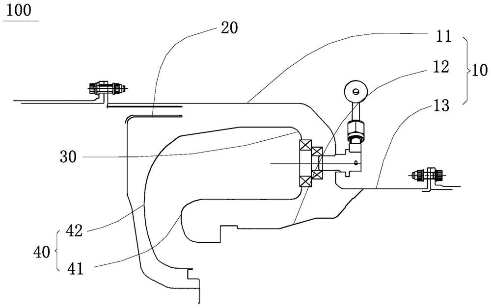
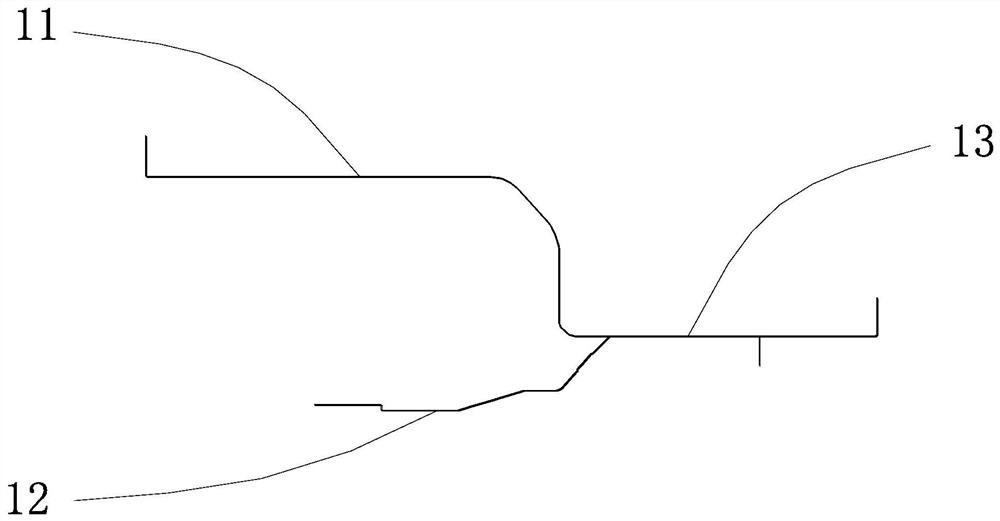
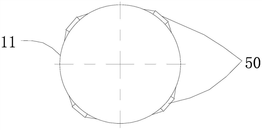
[0035] like figure 1 , figure 2 as well as image 3 As shown, the turboprop engine return combustion chamber 100 of this embodiment includes a combustion chamber casing 10, a diffuser 20, a flame tube 30, an exhaust elbow 40 and a mounting assembly 50. The combustion chamber casing 10 includes interconnected The combustion outdoor casing section 11, the gas turbine casing section 12 and the power turbine casing section 13, the flame tube 30 is accommodated in the cavity formed by the combustion outdoor casing section 11 and the gas turbine casing section 12, and the diffuser 20 is provided with It is upstream of the return combustion chamber and is used to provide high-pressure air for the flame tube 30. The exhaust elbow 40 is located at the airflow ...


PUM


Abstract

The invention discloses a return combustion chamber of a turboprop engine and a turboprop engine, comprising a combustion chamber casing, a diffuser, a flame tube, an exhaust elbow and an installation assembly. The combustion chamber casing comprises an interconnected combustion outdoor casing section, gas turbine casing section and power turbine casing section, the diffuser is located upstream of the return combustion chamber and is used to provide high pressure air for the flame tube, the exhaust elbow is at the airflow outlet of the flame tube and is used to dissipate the high temperature generated in the flame tube. The gas is folded and discharged. The casing section outside the combustion chamber, the casing section of the gas turbine and the casing section of the power turbine are connected to form an integral structure. The installation components are arranged on the outer circumferential wall of the casing of the combustion chamber, and the installation components are attached to the casing surface of the combustion chamber. The mid-section of the mounting assembly coincides with the section where the center of gravity of the engine is located. The turboprop engine returns to the combustion chamber of the invention, which satisfies the requirement of single-plane installation of the engine and realizes the installation requirement of the whole machine.

Description

technical field [0001] The present invention relates to the technical field of engine combustion chambers, in particular, to a return combustion chamber of a turboprop engine. In addition, the invention also relates to a turboprop engine. Background technique [0002] The recirculation combustion chamber can effectively shorten the length of the engine shaft, and is often used in the field of medium and small aero-engines. A typical return combustion chamber mainly includes a combustion chamber casing, a flame tube, an exhaust elbow (also known as a large / small elbow), a fuel nozzle, a fuel manifold, and an ignition nozzle. [0003] A turboprop is a type of aeroengine, and many turboprops use a recirculation combustion chamber structure. The various sections of the existing combustion chamber casing are fixedly connected by setting a mounting edge structure, and the use of the mounting edge structure for fixing leads to low concentricity and large engine vibration after as...

Claims


Application Information

Patent Timeline
Patent Type & Authority Patents(China)
IPC IPC(8): F23R3/54F23R3/60F02C3/14
CPCF23R3/54F23R3/60F02C3/145
Inventor 王启道康尧林柯陈彬刘瑶
Owner AECC HUNAN AVIATION POWERPLANT RES INST
Why Eureka
Try Eureka