Check patentability & draft patents in minutes with Patsnap Eureka AI!

Fuel cell system

A fuel cell system and fuel cell technology, which is applied to fuel cells, fuel cell additives, circuits, etc., can solve the problems of poor measurement accuracy, low responsiveness, and untimely correction of gas flow meters.

Pending Publication Date: 2021-07-20
TOYOTA JIDOSHA KK
View PDF2 Cites 0 Cited by
  • Summary
  • Abstract
  • Description
  • Claims
  • Application Information

AI Technical Summary

Problems solved by technology

This gas flowmeter is assumed to be used in an environment where the temperature and pressure do not change sharply, and the response to sharp changes in temperature and pressure is very low.
Therefore, in an environment where the temperature and pressure fluctuate rapidly as described above, there is a possibility that the correction of the gas flowmeter will not be timely, the measurement accuracy of the gas flowmeter will be poor, and the flow rate of the gas supplied to the fuel cell may not be accurately grasped.

Method used


Image

  • Fuel cell system
  • Fuel cell system

Examples


Embodiment Construction

[0030] 1. Fuel cell system

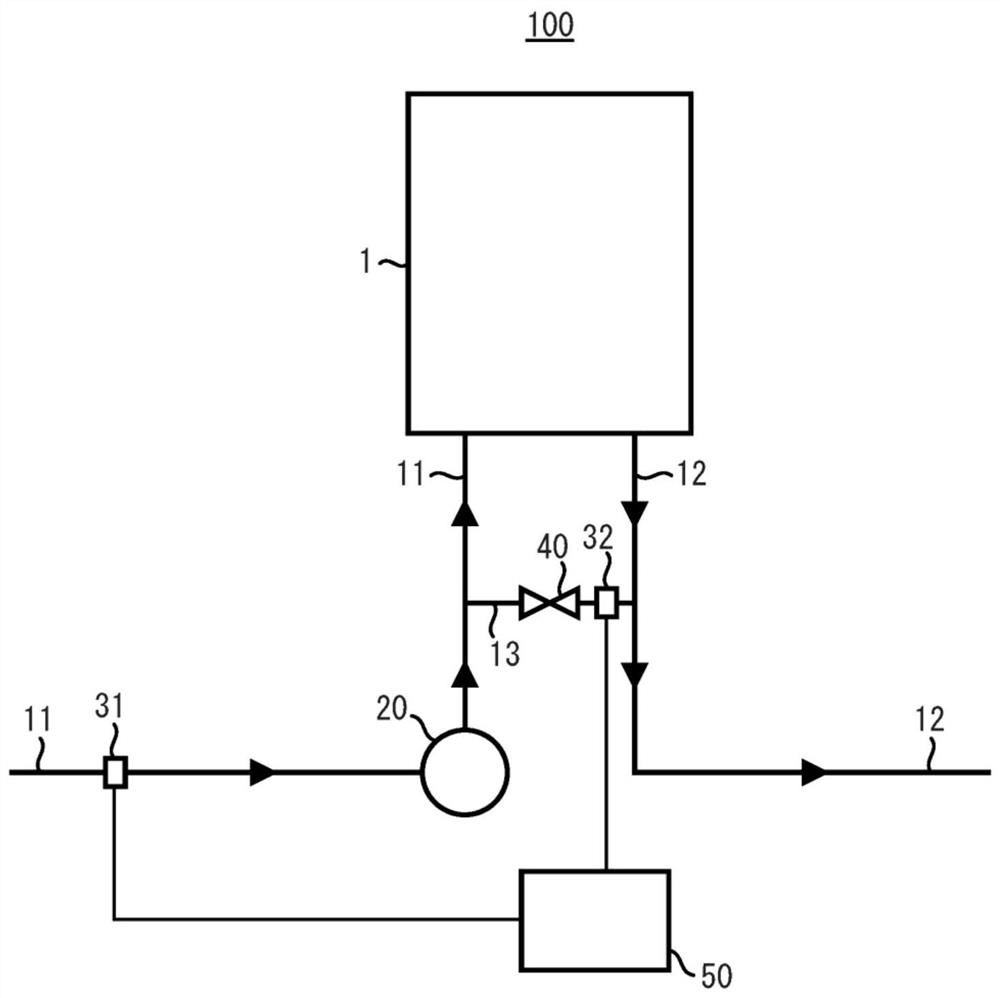
[0031] exist figure 1 The structure of the fuel cell system 100 is briefly shown in . like figure 1 As shown, the fuel cell 100 has: a fuel cell 1;

[0032] The first flow path 11 supplies cathode gas to the fuel cell 1;

[0033] The second flow path 12 discharges the cathode exhaust gas from the fuel cell 1;

[0034] The bypass flow path 13 is branched from the first flow path 11 and connected with the second flow path 12;

[0035] The compressor 20 is arranged in the first flow path 11;

[0036] The first flow meter 31 is set in the first flow path 11;

[0037] The flow regulating valve 40 is arranged in the bypass flow path 13;

[0038] The second flow meter 32 is installed in the bypass channel 13; and

[0039] The control unit 50 controls the flow rate of the cathode gas supplied to the fuel cell 1 .

[0040] The compressor 20 is arranged on the upstream side of the bypass channel 13 .

[0041] The first flow meter 31 is arranged on ...


PUM


Abstract

To precisely measure and control the amount of a cathode gas supplied to a fuel cell, a fuel cell system includes a fuel cell, a first flow passage through which a cathode gas is supplied to the fuel cell, a second flow passage through which a cathode off-gas is discharged from the fuel cell, a bypass flow passage which is bifurcated from the first flow passage and which is connected to the second flow passage, a compressor provided in the first flow passage, a first flowmeter provided in the first flow passage, a flow amount regulation valve provided in the bypass flow passage, a second flowmeter provided in the bypass flow passage, and a controller which controls the flow amount of the cathode gas supplied to the fuel cell, wherein the compressor is arranged on the upstream side of the bypass flow passage, the first flowmeter is arranged on the upstream side of the compressor, the second flowmeter is arranged on the downstream side of the flow amount regulation valve, and the controller controls the flow amount of the cathode gas supplied to the fuel cell based on the flow amount measured by the first flowmeter and the flow amount measured by the second flowmeter.

Description

technical field [0001] The present application discloses a fuel cell system. Background technique [0002] In order to improve the power generation performance of the fuel cell, it is desirable to supply the cathode gas and the anode gas to the fuel cell at necessary and sufficient flow rates. For this reason, it is necessary to be able to accurately grasp the respective flow rates of the cathode gas and the anode gas supplied to the fuel cell. For example, as disclosed in Patent Document 1, a flow meter may be provided at the cathode gas supply port of the fuel cell to measure the flow rate of the cathode gas supplied to the fuel cell. [0003] In addition, as disclosed in Patent Documents 1 and 2, when the cathode gas is supplied to the fuel cell, the pressure of the cathode gas may be increased by a compressor in some cases. [0004] Patent Document 1: Japanese Unexamined Patent Publication No. 2010-177123 [0005] Patent Document 2: Japanese Patent Laid-Open No. 2009-...

Claims


Application Information

Patent Timeline
IPC IPC(8): H01M8/04746H01M8/0438H01M8/04082H01M8/04089H01M8/04111
CPCH01M8/04111H01M8/04097H01M8/04104H01M8/04201H01M8/04395H01M8/04753H01M8/04089H01M8/0441H01M8/04141H01M8/0662Y02E60/50H01M8/04828
Inventor 高桥靖
Owner TOYOTA JIDOSHA KK
Features
  • R&D
  • Intellectual Property
  • Life Sciences
  • Materials
  • Tech Scout
  • Unparalleled Data Quality
  • Higher Quality Content
  • 60% Fewer Hallucinations
Learn More