Charging support and battery swap station

A charging stand and supporting stand technology, applied in battery circuit devices, current collectors, electric vehicles, etc., can solve the problems of poor electrical connection, low reliability, difficult to accurately locate the battery pack and charging stand, etc., and achieve charging stability. Excellent, good electrical connection reliability, good positioning accuracy

Pending Publication Date: 2021-07-20
BOZHON PRECISION IND TECH CO LTD
View PDF0 Cites 0 Cited by
  • Summary
  • Abstract
  • Description
  • Claims
  • Application Information

AI Technical Summary

Problems solved by technology

[0003] Currently, the battery pack is charged using a charging compartment or a charging stand. For a battery pack with a large size, it is difficult to achieve accurate positioning between the battery pack and the charging stand, so that there is a gap between the

Method used


Image

  • Charging support and battery swap station
  • Charging support and battery swap station
  • Charging support and battery swap station

Examples


Embodiment 1

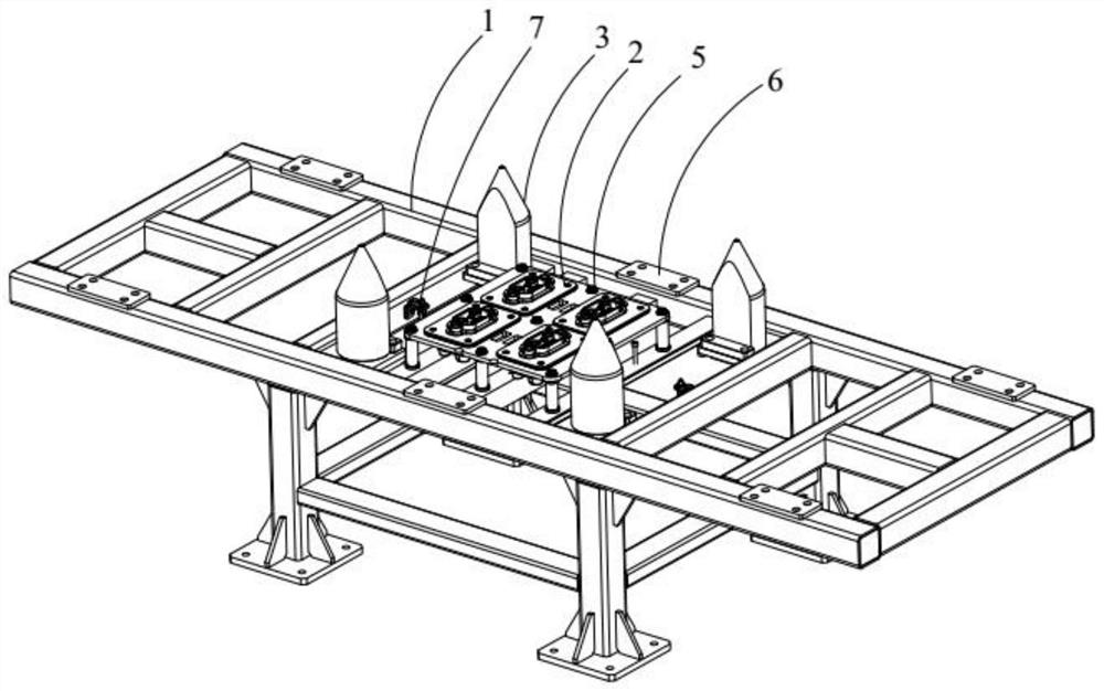
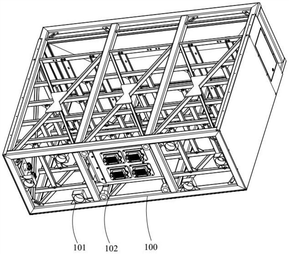
[0041] This embodiment provides a charging stand, such as Figure 1-Figure 2 As shown, it is used for charging the battery pack 100 . The charging stand includes a fixing seat, a supporting frame 1 and an electrical connection mechanism 2, and the supporting frame 1 is arranged on the fixing seat. The fixing base specifically includes four uprights, and the four uprights serve as feet to jointly carry the support frame 1 to realize support for the support frame 1 . The support frame 1 is a frame structure with light weight, and the support frame 1 is used to carry the battery pack 100 to ensure that the battery pack 100 has good support strength during charging. It should be noted that, in the existing battery pack, generally several battery cells are electrically connected together to form an integral battery pack, which is completely different from the structure of the battery pack 100 provided in the embodiment and the existing battery pack. The battery pack 100 of this e...

Embodiment 2

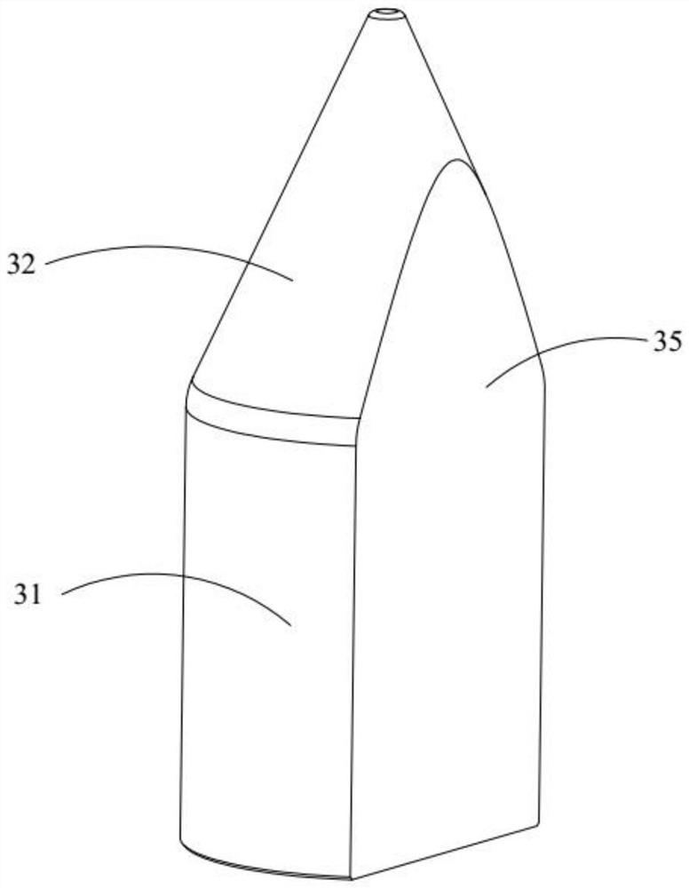
[0058] Compared with the first embodiment, this embodiment differs only in the specific structure of the first positioning column 3 , so the same parts will not be repeated here. like Figure 4 As shown, the support portion 31 of the first positioning column 3 provided in this embodiment is no longer a columnar structure, and the outer diameter of the support portion 31 gradually decreases toward the tip portion 32 , increasing the transition range. The tip portion 32 is no longer a cone structure, but the tip portion 32 is a columnar structure. It is equivalent to the opposite of the cylindrical shape and the tapered shape of the first embodiment. In this way, the support portion 31 can better transition to the tip portion 32, ensuring that the first positioning column 3 and the first positioning guide sleeve can Smooth introduction, good smoothness.

Embodiment 3

[0060] Compared with the second embodiment, the present embodiment differs only in the specific structure of the first positioning column 3 , so the same parts will not be repeated here. like Figure 5 As shown, the outer diameter of the support portion 31 in the first positioning column 3 provided in this embodiment gradually decreases toward the direction close to the tip portion 32 , and the outer diameter of the tip portion 32 gradually decreases toward the direction away from the support portion 31 . Optionally, the tip part 32 and the support part 31 can be integrally formed to form a conical structure. Compared with the second embodiment, this embodiment avoids the step between the support part 31 and the tip part 32 to affect the introduction effect, so that the transition from the bottom of the support part 31 to the top of the tip part 32 can be directly and smoothly.


PUM


Abstract

The invention belongs to the technical field of battery pack charging, and discloses a charging support and a battery swap station. The charging support comprises a fixed seat; a supporting frame;and a first positioning column. The supporting frame is arranged on the fixed seat, and the supporting frame is of a frame structure and is used for bearing a battery pack; the first positioning column comprises a supporting part and a tip part, the supporting part is arranged on the supporting frame, the tip part is arranged at the top of the supporting part, and first positioning guide sleeves are arranged at the bottoms of the battery packs respectively; and the tip part is configured to penetrate through the first positioning guide sleeve and be in sliding fit with the first positioning guide sleeve and used for coarse positioning of the battery pack, the supporting part is configured to penetrate through the first positioning guide sleeve and be in sliding fit with the first positioning guide sleeve and used for fine alignment of the battery pack, and the electric connection mechanism is arranged on the supporting frame and enables the battery pack to be electrically connected to the electric connection mechanism. According to the charging support, a rough alignment and fine alignment combined mode is adopted, the dual positioning effect of the battery pack is achieved, and the charging stability is good.

Description

technical field [0001] The invention relates to the technical field of battery pack charging, in particular to a charging stand and a power station. Background technique [0002] As people pay more and more attention to the environment, batteries have been widely used as clean energy. Because the built-in battery capacity of some electronic products is not enough, or according to the required electric energy, a battery pack with a larger capacity is required to meet the demand for rechargeable batteries. [0003] Currently, the battery pack is charged using a charging compartment or a charging rack. For a battery pack with a large size, it is difficult to achieve accurate positioning between the battery pack and the charging rack, so that there is a gap between the battery pack and the charging rack at the electrical connection interface. The large position deviation leads to poor electrical connection or even failure of the two, poor charging effect and low reliability, ma...

Claims


Application Information

Patent Timeline
IPC IPC(8): H02J7/00
CPCH02J7/0029H02J7/0042H02J7/0045
Inventor 李志清孙庆吴小平郭义志吴艳章
Owner BOZHON PRECISION IND TECH CO LTD
Why Eureka
Try Eureka