
Guiding and guarding system

A technology of guides and rolling mills, applied in the direction of guiding/positioning/alignment devices, etc., can solve problems such as floating up and down, not meeting the requirements of continuous rolling and rolling processes

Pending Publication Date: 2021-07-23
HEFEI BAISHENG SCI & TECH
View PDF3 Cites 0 Cited by
  • Summary
  • Abstract
  • Description
  • Claims
  • Application Information

AI Technical Summary

Problems solved by technology

Document 2 has the same problem as Document 1 in that it does not involve how the guide device reaches the position shown in the figure, because the suspension of the lower bracket 1 and upper bracket 3 must avoid the rolling mill stand before they can be hoisted to a fixed position. On the bracket 7, the stroke of the displacement of the nut 10 driven by the translation screw 8 and the displacement of the limit opening tile seat 11 is obviously shorter than the length of the suspension section of the lower arm 1 and the upper arm 3, that is to say, the guide device When falling to the height of the fixed bracket 7, it must move horizontally towards the material inlet of the roll to fall on the fixed bracket 7. This process is extremely difficult for a device weighing two tons. And the lower support arm 1 is fixed, and the upper support arm 3 moves up and down, resulting in the high rolling center, that is, the rolling line floats up and down, which is difficult to meet or not meet the requirements of the continuous rolling process

Method used


Image

  • Guiding and guarding system
  • Guiding and guarding system
  • Guiding and guarding system

Examples


Embodiment Construction

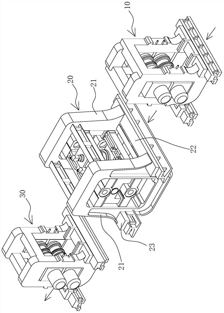
[0019] The guide system provided by the present invention is applicable to the continuous rolling system composed of the upper, middle and lower rolling mills 10, 20, 30, especially the diameter of the roll is up to 1m, and the billet to be rolled is 200mm*200mm or larger Bars with cross-sectional diameters of 75-350mm or even larger. Such as figure 1 , 2, there is a guide base between the upper and middle rolling mills 10 and 20 or the middle and lower rolling mills 20 and 30, and the extension direction of the track on the guide base is parallel to the rolling direction of the rolled piece. The direction of the arrow in the figure is The rolling direction of the rolled piece, the entrance guides and exit guides of the upper and middle rolling mills 10, 20 or the middle and lower rolling mills 20, 30 are displaced along the direction defined by the track and locked by the locking mechanism in the upper, middle and downstream Location at the entrance or exit of the rolling mi...


PUM


Abstract

The invention provides a guiding and guarding system. The guiding and guarding system is a rolling mill system consisting of an upstream rolling mill, a middle rolling mill and a downstream rolling mill, a guiding and guarding base is located between the upstream rolling mill and the middle rolling mill or between the middle rolling mill and the downstream rolling mill, and the extending direction of a rail on the guiding and guarding base is parallel to the advancing direction of rolled pieces. The inlet guiding and guarding part and the outlet guiding and guarding part of the upstream and midstream rolling mills or the midstream and downstream rolling mills are displaced along the direction limited by the track, and the positions of the inlet guiding and guarding part and the outlet guiding and guarding part at the inlets or the outlets of the upstream, midstream and downstream rolling mills are locked by a locking mechanism. The guiding and guarding base is arranged between the upstream rolling mill and the midstream rolling mill or between the midstream rolling mill and the downstream rolling mill, the track is arranged on the guiding and guarding base, when the guiding and guarding part is mounted in place or detached and moved, the guiding and guarding part can be vertically lifted to be separated from or fall to the guiding and guarding base through lifting equipment, and the process is not blocked or hindered by any environment. The problems that on one hand, the guiding and guarding part with the weight reaching two tons needs to be hoisted by hoisting equipment to bear the hoisting weight, and the guiding and guarding part needs to move towards an inlet or an outlet of a roller are thoroughly solved, and the problem that the large heavy-load guide is in place at the same time in the suspension state is thoroughly solved.

Description

technical field [0001] The present invention relates to a guide system of a rolling mill, specifically a guide system of a rolling mill for rolling bars. Background technique [0002] Bars are usually produced by rolling with a rolling mill. Guides are usually installed on the entrance and exit sides of the rolling mill. The guides guide and guard the materials to be rolled so that they can be introduced into the rolls and guided out of the rolled parts. Rolling area of ​​the roll. [0003] The rolling mill is used for rolling incoming billets with a cross-sectional size of 200x200mm or even larger. It can roll round steel or steel pipes with an outer diameter of 350mm or even larger. The distance between the upstream and downstream rolling mills is very limited, because the rolling raw materials The stroke speed is slow, and the distance between the rolling mills is too large, which is not conducive to the rapid arrival of the upstream rolling mill from the downstream roll...

Claims


Application Information

Patent Timeline
Patent Type & Authority Applications(China)
IPC IPC(8): B21B39/16
CPCB21B39/16
Inventor 娄霆王俊桂芳申晓庆张宏兵
Owner HEFEI BAISHENG SCI & TECH
Learn More