Lock clamp pressing head

A technology of indenter and lock clamp, which is applied to workpiece clamping devices, hand-held tools, manufacturing tools, etc., can solve problems such as troublesome and unsatisfactory use requirements, and achieve the effects of convenient use, high success rate, and convenient operation

Pending Publication Date: 2021-07-23
GUANGXI YUCHAI MASCH CO LTD
View PDF0 Cites 1 Cited by
  • Summary
  • Abstract
  • Description
  • Claims
  • Application Information

AI Technical Summary

Problems solved by technology

[0003] The existing lock clamp pressure head has certain disadvantages in use. When the existing lock clamp pressure head is pressed, the lock clamp pressure head is installed on the robot. During installation, it is necessary to use other fixtures to limit the position of the upper valve cover, which is troublesome. Can not meet people's requirements, for this reason, we propose a lock clip pressure head

Method used


Image

  • Lock clamp pressing head
  • Lock clamp pressing head
  • Lock clamp pressing head

Examples


Embodiment Construction

[0027] The following will clearly and completely describe the technical solutions in the embodiments of the present invention with reference to the accompanying drawings in the embodiments of the present invention. Obviously, the described embodiments are only some, not all, embodiments of the present invention.

[0028] In describing the present invention, it should be understood that the terms "upper", "lower", "front", "rear", "left", "right", "top", "bottom", "inner", " The orientation or positional relationship indicated by "outside", etc. is based on the orientation or positional relationship shown in the drawings, and is only for the convenience of describing the present invention and simplifying the description, rather than indicating or implying that the referred device or element must have a specific orientation, so as to Specific orientation configurations and operations, therefore, are not to be construed as limitations on the invention.

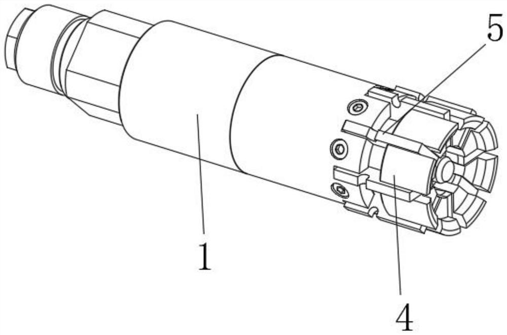
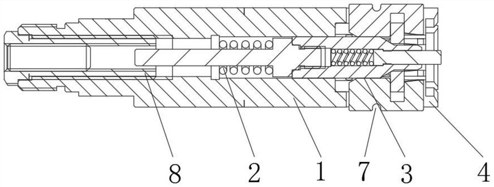
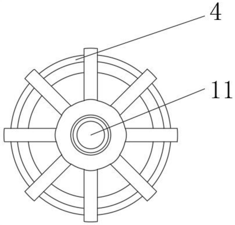
[0029] A lock clip pressu...


PUM


Abstract

The invention discloses a lock clamp pressing head. The lock clamp pressing head comprises a connecting rod and a pressing rod assembly, wherein a guide channel is formed in the connecting rod, a spring is arranged in the guide channel, a mounting opening communicating with the guide channel is formed in one end of the connecting rod, and a limiting device is arranged on the mounting opening; and the pressing rod assembly is located in the guide channel, and one end of the pressing rod assembly penetrates through the spring. According to the lock clamp pressing head, the position of an air valve upper cover can be limited, so that the air valve upper cover cannot deviate during press fitting, the position of the air valve upper cover does not need to be adjusted, press fitting can be directly carried out, the labor intensity is reduced, the press fitting efficiency is high, the success rate of press fitting is high, the clamping effect of the pressing head can be further improved, and therefore the stability of the air valve upper cover can be further improved; and different pressing heads can be replaced according to different air valve upper covers, so that the lock clamp pressing head is convenient to use, and a better use prospect is brought.

Description

technical field [0001] The invention relates to the technical field of engine assembly, in particular to a lock clamp pressing head. Background technique [0002] With the progress of the times, the engine has been widely used. There are many mechanisms on the engine, among which is the engine valve lock clip structure. At present, the most commonly used engine valve lock clip structure is the three-slot valve lock clip. Valve lock clips, people invented some lock clip pressure heads; [0003] The existing lock clamp pressure head has certain disadvantages in use. When the existing lock clamp pressure head is pressed, the lock clamp pressure head is installed on the robot. During installation, it is necessary to use other fixtures to limit the position of the upper valve cover, which is troublesome. Can't meet people's use requirement, for this reason, we propose a kind of lock clip pressing head. Contents of the invention [0004] The main purpose of the present inventi...

Claims


Application Information

Patent Timeline
Patent Type & Authority Applications(China)
IPC IPC(8): B25B11/02B25B27/02
CPCB25B11/02B25B27/02
Inventor 宁琨谭洪波农永新徐惠珍缪祥超康玉霞汪小强张栩覃贵财范焕林
Owner GUANGXI YUCHAI MASCH CO LTD
Why Eureka
Try Eureka