Accidental falling speed reduction structure for mine hoist

A mine hoist and deceleration structure technology, which is applied to mine hoisting equipment, elevators, transportation and packaging, etc., can solve the problems of insufficient safety and effectiveness, and achieve the effect of reducing risks and good deceleration effect

Pending Publication Date: 2021-07-23
吴开利
View PDF7 Cites 0 Cited by
  • Summary
  • Abstract
  • Description
  • Claims
  • Application Information

AI Technical Summary

Problems solved by technology

[0005] The purpose of the present invention is to provide a mine hoist accidental fall deceleration structure to solve the problem of insufficient safety and effectiveness when the mine hoist causes a stall and rapid fall

Method used


Image

  • Accidental falling speed reduction structure for mine hoist
  • Accidental falling speed reduction structure for mine hoist
  • Accidental falling speed reduction structure for mine hoist

Examples


Embodiment 1

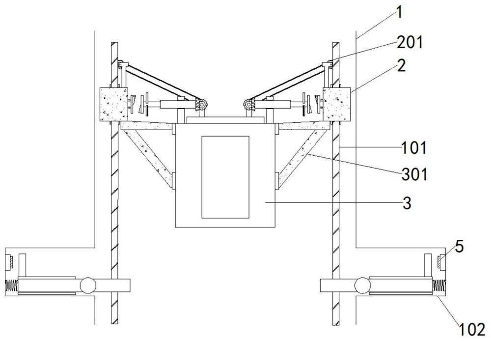
[0028] as attached figure 1 To attach Figure 9 Shown: an accidental fall deceleration structure for a mine hoist. The accidental fall deceleration structure for a mine hoist includes a mine 1 and a hoist 3. The mine 1 is equipped with a fall detection mechanism and a brake mechanism. Both sides of the inner wall of the mine 1 are Guide rails 101 are fixedly installed longitudinally, the hoist 3 is arranged between two sets of guide rails 101, support frames 301 are fixedly installed on both sides of the hoist 3, and the casing 2 is fixedly installed above the support frame 301, and the connection between the casing 2 and the guide rails 101 The upper parts of the two shells 2 are rotatably connected to the gear 201 through the bracket, and the guide rail 101 is provided with a tooth groove, and the gear 201 meshes with the tooth groove.

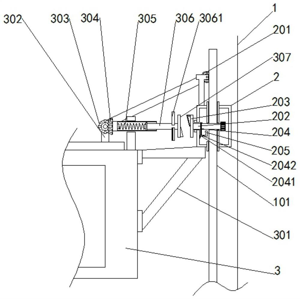
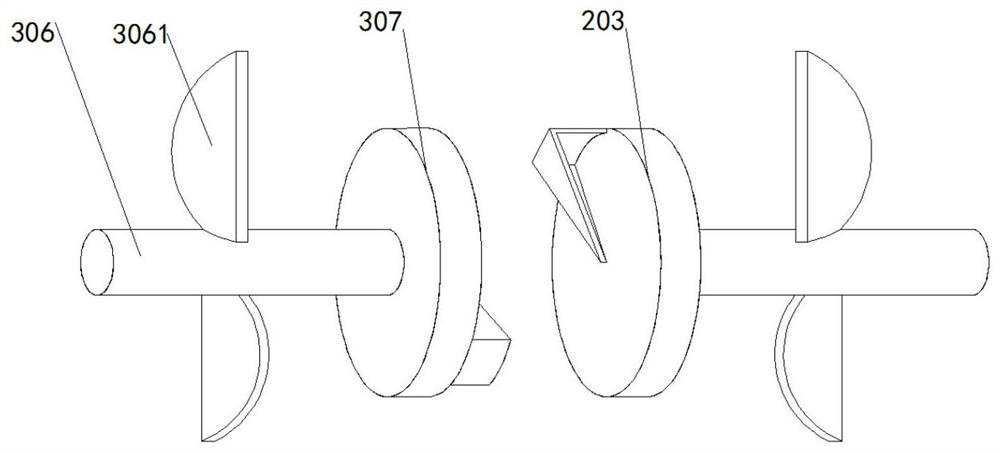
[0029] as attached figure 1 , 2 , shown in 6 and 7: the fall detection mechanism includes bevel gear one 303, bevel gear two 304, hollow...

Embodiment 2

[0035] Such as figure 1 , 5 As shown: a groove 102 is arranged inside the mine shaft 1 .

[0036] The present invention also includes a signal-triggered deceleration mechanism. The signal-triggered deceleration mechanism is located in the groove 102. The signal-triggered deceleration mechanism includes a signal transmitter, a signal receiver, and a deceleration mechanism. The deceleration mechanism includes an electromagnet 5, a chute 4, Sliding plate 401, compression spring 402, iron plate 403, electromagnet 5 are installed on the side of the groove 102 inner wall away from the mine, the bottom of sliding plate 401 is provided with a slider, and the slider is equipped with a chute 4 and is arranged at the bottom of the groove 102 On the wall, an iron plate 403 is fixedly installed on the top of the sliding plate 401, and the end of the sliding plate 401 away from the mine is connected to the inner wall of the groove 102 through a compression spring 402, and the signal transm...


PUM


Abstract

The invention provides an accidental falling speed reduction structure for a mine hoist. The accidental falling speed reduction structure for the mine hoist comprises a mine and the hoist, a falling detection mechanism and a braking mechanism are arranged in the mine, guide rails are longitudinally and fixedly installed on the two sides of the inner wall of the mine, and the hoist is arranged between the two guide rails. Supporting frames are fixedly mounted on the two sides of the hoist correspondingly, and the two supporting frames are symmetrically arranged with respect to the central axis of the hoist. According to the accidental falling speed reduction structure for the mine hoist, the lever principle is utilized, a steel wire rope, a movable rod and brake pads are arranged, the steel wire rope can pull the movable rod at the other end, the movable rod rotates on the outer side of a rotating shaft, the brake pads at the other end of the movable rod make contact with the surfaces of the guide rails at the moment, the claw hammer-shaped brake pads can rub the surfaces of the guide rails, and the hoist is decelerated; and when the hoist stalls and falls, the falling speed is prevented from being too high, and a better speed reduction effect is achieved.

Description

technical field [0001] The invention relates to the technical field of mine hoists, in particular to an accidental fall deceleration structure for mine hoists. Background technique [0002] Mine hoist refers to the main transportation equipment that connects the underground and the ground in mining engineering. The mine hoist is a hoisting machine that is installed on the ground and drives the hoisting container to run along the shaft or ramp by means of a wire rope. It is used for lifting coal, ore and gangue in vertical shafts and inclined shafts, as well as lifting personnel, lowering materials, tools and equipment, etc. [0003] Because the existing mine hoist has an accident in use, the hoist will cause a stall and a rapid fall. The existing deceleration structure requires the control electronic instrument of the center console to carry out instruction control, and the response of this control device is not sensitive enough when it is used. , The safety is poor, and t...

Claims


Application Information

Patent Timeline
IPC IPC(8): B66B5/18B66B5/26B66B19/06
CPCB66B5/18B66B5/26B66B19/06
Inventor 吴开利
Owner 吴开利
Why Eureka
Try Eureka