C-type starting forward curve multi-blade centrifugal fan impeller and manufacturing method

A centrifugal fan, a pre-starting technology, applied to mechanical equipment, machines/engines, liquid fuel engines, etc., can solve problems such as unreasonable flow passages between blades, failure to form arc lines, and reduced aerodynamic performance to achieve good blades. Between the flow channels, to achieve the effect of drag reduction and improve the effect of flow conditions

Active Publication Date: 2021-07-23
XI AN JIAOTONG UNIV
View PDF5 Cites 1 Cited by
  • Summary
  • Abstract
  • Description
  • Claims
  • Application Information

AI Technical Summary

Problems solved by technology

Due to the limitation of the characteristics of the arc itself, the center arc of the blade formed by single arc or multiple arcs only has the structure of arc radius, arc center angle and apex circle radius, which makes the design freedom of the shape of the flow channel between the blades relatively small. Low, can not form a reasonable streamlined blade mid-arc line, making the flow path between the blades relatively unreasonable, there are a lot of vortex areas between the flow paths of such blades due to flow separation, resulting in large flow loss, and the aerodynamic performance is also corresponding reduce

Method used


Image

  • C-type starting forward curve multi-blade centrifugal fan impeller and manufacturing method
  • C-type starting forward curve multi-blade centrifugal fan impeller and manufacturing method
  • C-type starting forward curve multi-blade centrifugal fan impeller and manufacturing method

Examples


Embodiment Construction

[0045] The present invention is described in further detail below in conjunction with accompanying drawing:

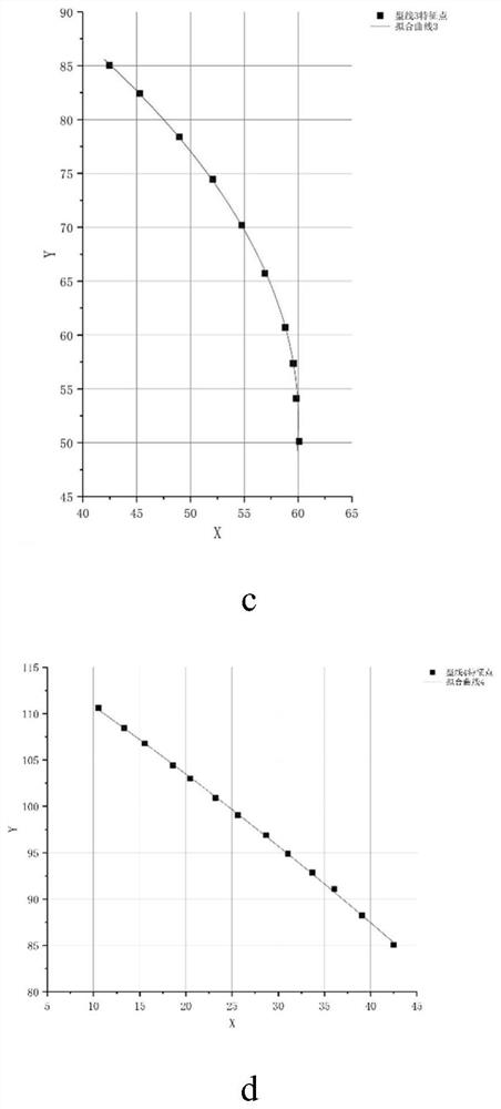
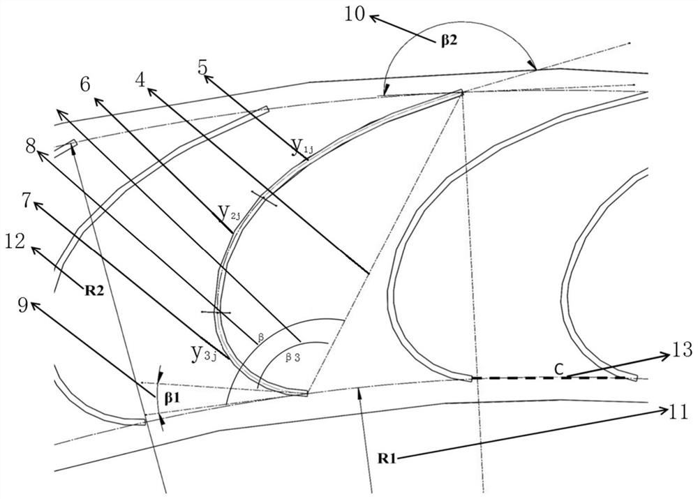
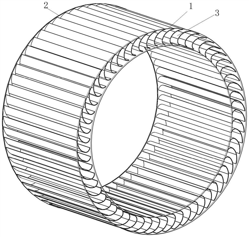
[0046] Such as figure 1 , figure 2 As shown, a C-type starting forward curved multi-blade centrifugal fan impeller includes an impeller front disk 1, an impeller rear disk 2, and a circular array of blades 3 between the impeller front disk and the impeller rear disk, and the blades 3 are perpendicular to the width of the impeller. The section in the direction is a C-shaped section, and the middle arc of the C-shaped section is the first curve y 1j 5. The second curve y 2j 6 and the third curve y 3j 7 Fitting curves connected in sequence, that is, the equation of the center line of the fish body;

[0047]

[0048] where the first curve y 1j The end of 5 is the blade trailing edge, the third curve y 3j The end of 7 is the leading edge of the blade; the line between the trailing edge of the blade and the leading edge of the blade is the blade chord length 4, and t...


PUM


Abstract

The invention discloses a C-type starting forward curve multi-blade centrifugal fan impeller and a manufacturing method. A fish center line equation of a cyrinoid C type starting curve section is obtained through a reverse reconstruction way to form an impeller front disc, an impeller rear disc and an impeller structure which is arranged between the impeller front disc and the impeller rear disc in the form of a circular array, wherein sections perpendicular to the width directions of blades are C type sections; a blade structure formed by fitting mean lines of the C type sections to the curve is on the mean lines of the blades of the multi-blade centrifugal fan; the formed impeller can improve gas flow in an impeller runner on the premise of increasing air quantity of the fan, reduces flow separation, in the runner among the blades, of the gas flow, inhibits vortexes, and reduces pressure pulsation and turbulent pulsation on the surfaces of the blades, so that air quantity and air pressure of the fan are increased, pneumatic noises of the fan are reduced, damping effect can be effectively realized, and the effect of effectively reducing the pneumatic noises of the impeller can be achieved while air and pressure are increased.

Description

technical field [0001] The invention belongs to a multi-blade centrifugal fan impeller, in particular to a C-type forward-bending multi-blade centrifugal fan impeller and a preparation method thereof. Background technique [0002] Multi-blade centrifugal fans have the characteristics of compact structure, high pressure coefficient, and large flow coefficient. Therefore, multi-blade centrifugal fans are widely used in the fields of air conditioners, range hoods and other home appliances. There are increasingly higher requirements for the air volume and pressure of multi-blade centrifugal fans. The impeller is the main working part of the multi-blade centrifugal fan, and its performance determines the air volume, wind pressure and noise of the fan. When the multi-blade centrifugal fan is running, the impeller is the most important working part of the multi-blade centrifugal fan. When the airflow flows through the impeller blade channel, a large turbulent flow will be generate...

Claims


Application Information

Patent Timeline
Patent Type & Authority Applications(China)
IPC IPC(8): F04D29/30F04D25/08F04D17/16F04D29/44F04D29/66
CPCF04D25/08F04D17/16F04D29/30F04D29/441F04D29/666Y02E10/72
Inventor 刘小民王加浩田晨晔席光
Owner XI AN JIAOTONG UNIV
Why Eureka
Try Eureka