
Boiler pipeline secondary air on-line monitoring system

A monitoring system and secondary air technology, applied in the direction of measuring fluid velocity using differential pressure, can solve problems such as inability to meet, large variation gap, boiler AGC regulation risk, etc., to reduce the probability of non-stop accidents and improve measurement accuracy and stability, the effect that is conducive to long-term safe operation

Pending Publication Date: 2021-07-23
HUANENG (GUANGDONG) ENERGY DEV CO LTD
View PDF0 Cites 0 Cited by
  • Summary
  • Abstract
  • Description
  • Claims
  • Application Information

AI Technical Summary

Problems solved by technology

[0002] Due to the short length of the straight pipe section used for measurement, the layout of the secondary air duct adopted by the existing boiler cannot meet the requirements for the position of the measurement section in the "Performance Test Regulations for Power Plant Boilers" (GB10184-88), and cannot obtain Accurate parameter data, coupled with the existence of vortex and backflow in the flow field in the secondary air duct of the boiler, and the change of unit load during operation, the pressure at the outlet of the secondary fan will also be adjusted accordingly, resulting in The flow velocity is redistributed, the situation in the flow field changes quickly, and the change gap is large
[0003] At different positions of the secondary air duct cross-section, there are great differences in the flow velocity distribution of the flow field inside the air duct. At present, the secondary wind measurement of the power plant adopts the wing-type measurement system, and the pressure-taking holes are extremely easy to be blocked, and the flow resistance is large. Severe wear and tear, unable to respond to changes in boiler working conditions in real time, bringing huge risks to boiler AGC regulation

Method used


Image

  • Boiler pipeline secondary air on-line monitoring system
  • Boiler pipeline secondary air on-line monitoring system
  • Boiler pipeline secondary air on-line monitoring system

Examples


Embodiment Construction

[0032] The present invention will be further described below in combination with specific embodiments. Wherein, the accompanying drawings are only for illustrative purposes, showing only schematic diagrams, rather than physical drawings, and should not be construed as limitations on this patent; in order to better illustrate the embodiments of the present invention, some parts of the accompanying drawings will be omitted, Enlargement or reduction does not represent the size of the actual product; for those skilled in the art, it is understandable that certain known structures and their descriptions in the drawings may be omitted.

[0033] In the drawings of the embodiments of the present invention, the same or similar symbols correspond to the same or similar components; The orientation or positional relationship indicated by etc. is based on the orientation or positional relationship shown in the drawings, and is only for the convenience of describing the present invention an...


PUM

PropertyMeasurementUnit
Thicknessaaaaaaaaaa

Abstract

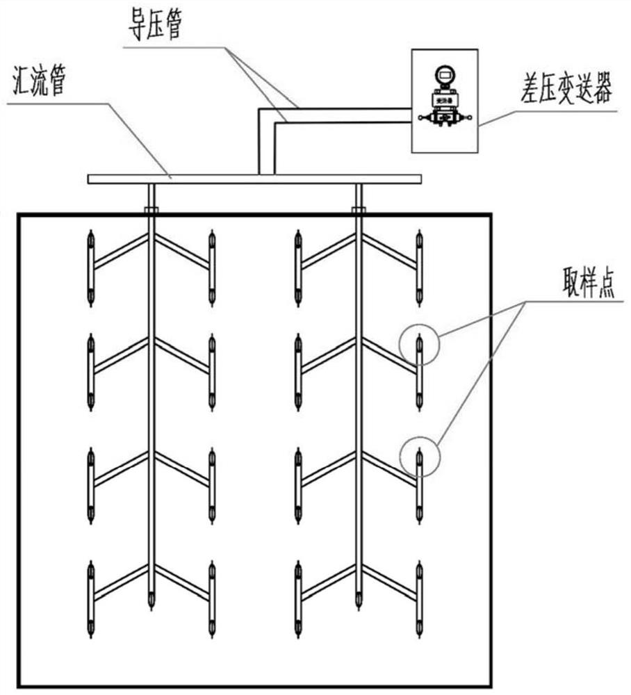
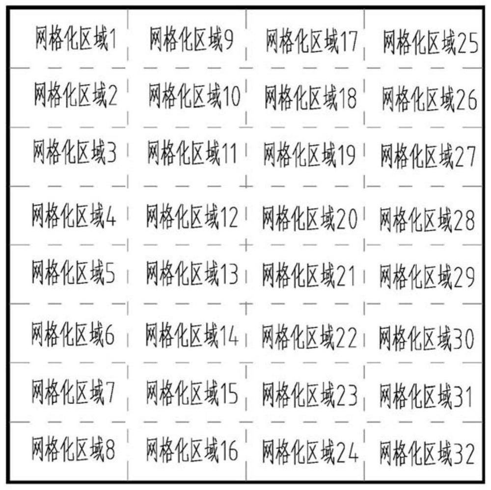
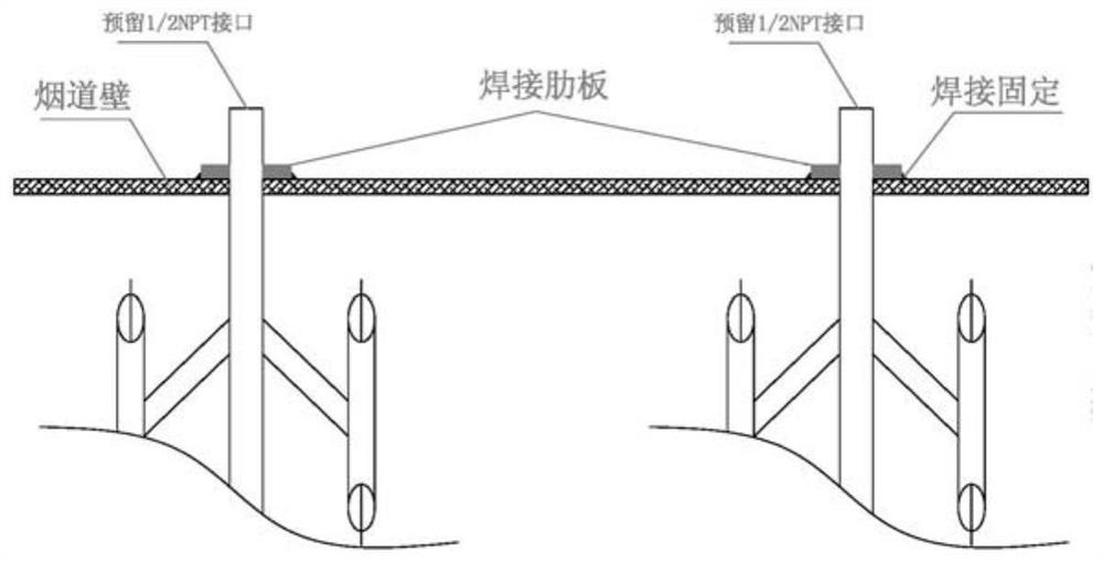
The invention belongs to the technical field of boiler air duct secondary air monitoring and relates to a boiler pipeline secondary air on-line monitoring system. According to the system, a cross section array of a secondary air duct straight pipe section is equally divided into a plurality of sampling areas; the sampling areas in the section of a secondary air duct are correspondingly provided with sampling points, and the sampling points are provided with sampling probes; a sampling mechanism performs weighted averaging on the high and low voltage signals of the corresponding sampling areas obtained by the sampling probes to obtain differential pressure signals; and analysis signals obtained after the differential pressure signals pass through a signal processor are outputted and are fed back to an upper control system. According to the online monitoring system provided by the invention, the sampling point probes are arranged in each sampling areas by adopting a gridding sampling design, and the flow velocity signal of each sampling area in the air duct is subjected to weighted average, so that the real-time average flow velocity in the air duct can be obtained; measurement distortion under the conditions of serious turbulent flow and turbulent flow field is effectively solved, and the air volume and the flow field in the air duct can be rapidly and accurately monitored.

Description

technical field [0001] The present invention relates to the technical field of boiler air duct secondary air monitoring, and more specifically, relates to an online monitoring system for secondary air of boiler pipes Background technique [0002] Due to the short length of the straight pipe section used for measurement, the layout of the secondary air duct adopted by the existing boiler cannot meet the requirements for the position of the measurement section in the "Performance Test Regulations for Power Plant Boilers" (GB10184-88), and cannot obtain Accurate parameter data, coupled with the existence of vortex and backflow in the flow field in the secondary air duct of the boiler, and the change of unit load during operation, the pressure at the outlet of the secondary fan will also be adjusted accordingly, resulting in The flow velocity is redistributed, and the situation in the flow field changes quickly and the change gap is large. [0003] At different positions of the...

Claims


Application Information

Patent Timeline
IPC IPC(8): G01P5/14
CPCG01P5/14
Inventor 杨扬生纪洁虹唐一多张家宽林泽鸿王彬
Owner HUANENG (GUANGDONG) ENERGY DEV CO LTD
Learn More