Touch substrate and display device

A substrate and touch technology, applied in instruments, electrical digital data processing, input/output process of data processing, etc., can solve the problems affecting the working performance of the touch substrate, signal crosstalk, etc., to improve the working performance and improve the signal-to-noise ratio, the effect of reducing crosstalk

Pending Publication Date: 2021-07-23
SHENZHEN CHINA STAR OPTOELECTRONICS SEMICON DISPLAY TECH CO LTD
5 Cites 0 Cited by

AI-Extracted Technical Summary

Problems solved by technology

However, for the current touch substrate that synchronously integrates the light control sensor and the touch sensor, when the light control sensor and the touch s...

Method used

[0031] The embodiment of the present invention can shield the signal crosstalk between the touch sensing electrode and the reading line by setting the signal shielding device between the touch unit and the optical unit, improve the signal-to-noise ratio, and reduce the light control sensor and touch control. The crosstalk between sensors improves the working performance of the touch substrate.
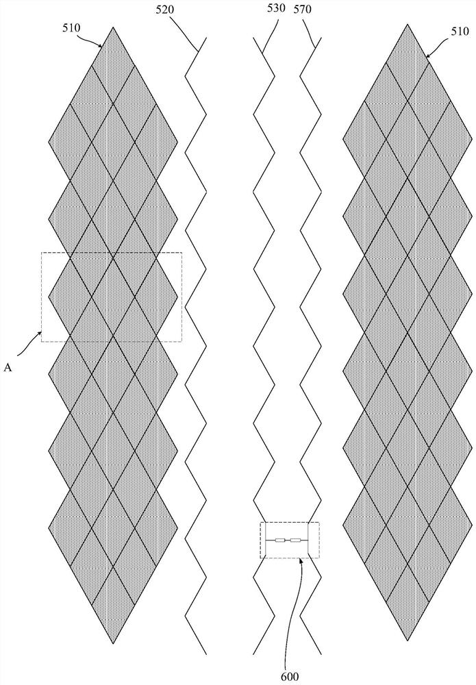
[0035] In this embodiment, the signal shielding device includes a signal shielding line 520, and the signal shielding line 520 is arranged between the touch sensing electrode 510 and the signal reading line 530; wherein, the signal The shielding wire 520 is disposed on the same layer as the touch sensing electrode 510 and the signal reading wire 530 , please refer to FIG. 1 for details. The signal shielding line 520 is parallel to the touch sensing electrode 510, and the signal shielding line 520 is parallel to the signal reading line 530, which can better shield the touch sensing electrode 510 from the signal reading Signal crosstalk between lines 530.
[0037] In this embodiment, the distance between the signal shielding line 520 and the touch sensing electrode 510 is smaller than the distance between the signal shielding line 520 and the signal reading line 530, please refer to FIG. 3 for details. In actual work, touch detection is often used, such as screen touch, etc., the operating frequency of the touch sensing electrode 510 is relatively frequent, and the voltage changes frequently. The electrodes 510 can better shield the touch sensing electrodes 510 from electromagnetic signals, improve the signal-to-noise ratio, reduce the crosstalk between the light control sensor and the touch sensor, and improve the working performance of the touch control substrate 100 .
[0043] In this embodiment, the orthographic projection of the signal shielding line 520 and the signal reading line 530 on the substrate 200 is a broken line, and the touch sensing electrode 510 on the substrate 200 The orthographic projection is grid lines, see Figure 3 for details. The orthographic projection of the signal shielding line 520 on the substrate 200 is a broken line, and a single signal shielding line 520 can shield the space between the touch sensing electrode 510 and the signal reading line 530 The effect of the signal crosstalk, the folded line can increase the corresponding area of ​​shielding, and enhance the shielding effect, the orthographic projection of the signal reading line 530 on the substrate 200 is a folded line, which can also increase the corresponding area of ​​the shielding, and enhance the shielding Effect. The orthographic projection of the touch sensing electrodes 510 on the substrate 200 is a grid line, which can increase the corresponding area of ​​shielding, enhance the shielding effect, and reduce the resistance of the touch sensing electrodes 510. The failure rate of the touch sensing electrode 510 can be reduced, and any line can work normally when it is turned on.
[0045] In this embodiment, the adjacent signal shielding lines 520 may be arranged in paral...

Abstract

The embodiment of the invention discloses a touch substrate and a display device. The touch substrate comprises a substrate body and a touch layer arranged on the substrate body. The touch layer comprises a plurality of touch units and a plurality of optical units, each touch unit comprises a touch sensing electrode, each optical unit comprises a signal reading line, the touch sensing electrodes and the signal reading lines are oppositely arranged, and each signal reading line is arranged between every two adjacent touch sensing electrodes, wherein the touch layer further comprises a signal shielding device arranged between the touch unit and the optical unit, and the signal shielding device is arranged close to the touch induction electrode or the signal reading line. According to the embodiment of the invention, the signal shielding device is arranged between the touch unit and the optical unit, so that the signal crosstalk between the touch sensing electrode and the reading line can be shielded, the signal-to-noise ratio is improved, the crosstalk between the light-operated sensor and the touch sensor is reduced, and the working performance of the touch substrate is improved.

Application Domain

Input/output processes for data processing

Technology Topic

PhysicsDisplay device +4

Image

  • Touch substrate and display device
  • Touch substrate and display device
  • Touch substrate and display device

Examples

  • Experimental program(1)

Example Embodiment

[0026] Next, the technical solutions in the embodiments of the present invention will be described in connext of the embodiments of the present invention, which is apparent from the embodiments of the present invention, and is apparent from the embodiments of the present invention, not all of the embodiments of the invention. Based on the embodiments of the present invention, those skilled in the art are in the range of the present invention in the scope of the present invention without all other embodiments obtained without creative labor. In addition, it should be understood that the specific embodiments described herein are intended to illustrate and explain the invention and is not intended to limit the invention. In the present invention, when not explained, the orientation words used, such as "upper" and "under" generally refer to the upper and lower and bottoms of the apparatus in actual use or working state, specifically in the drawing direction in the drawings. And "inner" and "outside" are for the contour of the device.
[0027] In recent years, the integration of optical control sensors and touch sensors is integrated to the touch substrate thinning. However, when the touch substrate, the optical control sensor, and the touch sensor synchronously integrated with the optical control sensor and the touch sensor are simultaneously operated, the parasitic is easily generated between the electrodes of the touch sensor and the optical control sensor. Capacitor, resulting in signal crosstalk, affecting the performance of the touch substrate.
[0028] See Figure 1 ~ 6 The embodiment of the present invention provides a touch substrate 100 including a substrate 200 and a touch layer provided on the substrate 200;
[0029] The touch layer includes a plurality of touch units and a plurality of optical units 600 including a touch sensing electrode 510, the optical unit 600 includes a signal read wire 530, the touch sensing electrode 510 and The signal read wire 530 is disposed relatively, and the signal read wire 530 is disposed between the adjacent two of the touch sensing electrodes 510;
[0030] The touch layer further includes a signal shield device disposed between the touch unit and the optical unit 600, the signal shield device near the touch sensing electrode 510 or the signal read line 530 set up.
[0031] The embodiment of the present invention can shield signal crosstalk between the touch sensing electrode and the reading line between the touch unit and the optical unit, and the signal-to-noise ratio can be shielded between the touch sensing electrodes and the reading line, which reduces the optical control sensor and the touch sensor. Crosstalk, improve the performance of the touch substrate.
[0032] The technical solutions of the present invention will now be described in connection with specific embodiments.
[0033] The touch substrate 100 includes a substrate 200 and a touch layer provided on the substrate 200; the touch layer includes a plurality of touch units and a plurality of optical units 600, the touch unit including touch The induction electrode 510 includes a signal read wire 530 that is configured with the signal read wire 530, the signal read wire 530 is disposed in adjacent two. The control sensing electrode 510 is between; wherein the touch layer further comprises a signal shield device disposed between the touch unit and the optical unit 600, the signal shield device near the touch sensing electrode 510 or The signal read wire 530 is disposed.
[0034] In 1 ~ Image 6 In all fills only to distinguish different film layers or different wires, do not represent specific structures in the electric wire, for example image 3 In the identification area A, only three complete grids of the touch sensing electrode 510 are included in this description.
[0035] In this embodiment, the signal shielding device includes a signal shield line 520, which is disposed between the touch sensing electrode 510 and the signal reading line 530; wherein the signal shield line 520 For details, please refer to the same layer with the touch sensing electrode 510 and the signal read line 530. figure 1. The signal shield line 520 is parallel to the touch sensing electrode 510, and the signal shield line 520 is parallel to the signal reading line 530, which can better shield the touch sensing electrode 510 and the signal read. The signal crosstalk between the line 530.
[0036] In this embodiment, the signal shield line 520 is a constant voltage power line that is electrically connected to a constant voltage source. The signal shield line 520 may be a COM line or an SVDD line or an SVGG line, which may be a COM line or an SVDD line or an SVGG line, and the signal shield line 520 of the constant voltage can form an electromagnetic signal shielding. Further reduction of signal crosstalk between the touch sensing electrode 510 and the reading line, lifting signal-to-noise ratio, reducing the crosstalk between the optical control sensor and the touch sensor, and lift the working performance of the touch substrate 100.
[0037] In this embodiment, the spacing of the signal shield line 520 and the touch sensing electrode 510 is smaller than the spacing of the signal shield line 520 and the signal reading line 530, please refer to image 3. In actual work, touch detection, such as screen touch, etc., the touch sensing electrode 510 is often used, and the operating frequency of the touch sensing electrode 510 is more frequent, and the voltage variation is more frequent, and the signal shield line 520 is disposed adjacent to the touch sensing. The electrode 510 can better make the touch sensing electrode 510 as an electromagnetic signal shield, lift the signal-to-noise ratio, reduce the crosstalk between the optical control sensor and the touch sensor, and improve the working performance of the touch substrate 100.
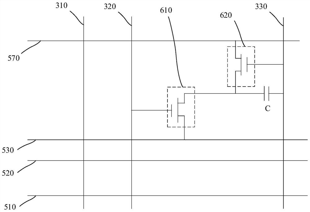
[0038]In this embodiment, the touch substrate 100 includes a first metal layer on the substrate 200 and a second metal layer located on the first metal layer; the first metal layer comprises a plurality of touch The transmitting electrode 310, a plurality of gate lines 320, and a plurality of first common electrode lines 330, the second metal layer comprising a plurality of said touch sensing electrodes 510, a plurality of said signal read wires 530 and a plurality of Two common electrode lines 570; wherein the touch transmit electrode 310 intersects the touch sensing electrode 510, please refer to Figure 4 The first common electrode line 330 intersects the second common electrode line 570, you can refer to the circuit diagram, figure 2. The first common electrode line 330 can be an SVGG line, the second common electrode line 570 can be an SVDD line.
[0039] In this embodiment, the touch substrate 100 further includes a first insulating layer 400 between the first metal layer and the second metal layer, for details, please refer to figure 1.
[0040] In this embodiment, the touch substrate 100 includes a plurality of first zone 810 and a plurality of second zones 820; the touch sensing electrode 510 and the position crossing the touch transmit electrode 310 are located in the first Inside the zone 810, the touch unit is located within the first zone 810, the touch sensing electrode 510 corresponding to the intermediate position of the touch emission electrode 310 corresponding to the second region 820, the optical Unit 600 is located within the second region 820. The touch sensing electrode 510 and the touch transmit electrode 310 periodically arranged in each cycle, wherein the optical unit 600 is located within the second zone 820, that is, a central portion, and the touch sensing unit. Located in the first zone 810, that is, a square area, the unlabeled area is a virtual area, and for details, please refer to Figure 4. The structure can be fully utilized, while achieving touch functionality, there is also a space to implement optical control.
[0041] In this embodiment, the optical unit 600 includes a switching transistor 610, a photosensitive transistor 620, and a storage capacitor C; the first gate 321 of the switching transistor 610 is electrically connected to the gate line 320, the switching transistor 610 The first source 541 is electrically connected to the signal reading line 530, and the first drain 551 of the switching transistor 610 is electrically connected to the second source 542 of the photosensitive transistor 620, and the second source of the photosensitive transistor 620 is second. The drain 552 is electrically connected to the second common electrode line 570, and the second gate 322 of the photosensitive transistor 620 is electrically connected to the first common electrode line 330, the first drain 551 and the first The common electrode line 330 forms the storage capacitor C, for details, please refer to figure 2. The optical unit 600 can include 2T1C or 3T1C or 4T1C or 5T1c, which may not be limited.
[0042] In this embodiment, the switching transistor 610 further includes a first active unit 561, and the photosensitive transistor 620 further includes a second active unit 562, the first active unit 561 located at the first gate 321 and Between the first source 541 and the first drain 551, the second active unit 562 is located at the second gate 322 and the second source 542 and the second drain 552. Between, the material of the first active unit 561 and / or the second active unit 562 includes hydrogenated amorphous silicon, for details, please refer to figure 1. For example, in 2T1c, the active unit in 2T, that is, the material of the photosensitive transistor 620 and / or the switching transistor 610 comprises hydrogenated amorphous silicon, which improves the photosensitive and reaction efficiency of the optical unit 600, and improves the touch substrate. 100 workability.
[0043] In this embodiment, the signal shield line 520 and the signal reading line 530 are positive projection on the substrate 200 as a fold line, and the touch sensing electrode 510 is projected on the substrate 200. Grid line, please refer to image 3. The signal shield line 520 is a positive projection of the substrate 200 as a fold line, and the signal shield line 520 can be shielded between the touch sensing electrode 510 and the signal reading line 530. The effect of the signal crosstalk, the fold line can increase the corresponding area of ​​the shield, enhance the shielding effect, the signal reading line 530 is a positive projection on the substrate 200, and can increase the corresponding area of ​​the shield, enhance shield Effect. The touch sensing electrode 510 is a grid line on the substrate 200, i.e., the corresponding area of ​​the shield, enhance the shielding effect, but also reduce the resistance of the touch sensing electrode 510, but also The failure rate of the touch sensing electrode 510 can be reduced, and any line is turned on.
[0044] In this embodiment, the signal shield line 520 is projected on the substrate 200 as a grid line, for details, please refer to Figure 5. Further increase the corresponding area of ​​the shield, enhance the shielding effect, and reduce the resistance of the signal shield line 520, and can also reduce the failure rate of the signal shield line 520, and any line is turned on.
[0045] In this embodiment, adjacent the signal shield line 520 can be in parallel. The resistance of the signal shield line 520 can be reduced, but also increase the voltage stability of the wire, enhance the effect of shielding the signal crosstalk between the touch sensing electrode 510 and the signal reading line 530.
[0046] In this embodiment, the SVDD line and the SVGG line can be connected via a well-electrically connected. It is conducive to the stability of the voltage and reduces the electric wire resistance.
[0047] In this embodiment, the voltage of the touch transmit electrode 310 is fluctuated between 0V to 30V, wherein the touch sensing electrode 510 is a fluctuation state. The signal shield line 520 is a fixed voltage having a voltage range of -20V to 20V. Both the SVDD line and the SVGG line are fixed voltage, and the voltage range can range between -10V ~ 10V. The voltage range of the gate line is -15V to 15V.
[0048] In the present embodiment, since the touch transmit electrode 310 and the touch sensing electrode 510 are present, the touch transmit electrode 310 signal is a fluctuation signal of the cycle, thereby touching the signal reading line of the sensing electrode 510 and the optical control unit 530. There is an influence of signal crosstalk, and after the touch sensing electrode 510 is added between the touch sensing electrode 510 and the signal reading line 530, the parasitic capacitance between the touch sensing electrode 510 and the signal reading line 530 is reduced to 1ff or less, thereby Basically, the signal crosstalk between the touch sensing electrode 510 and the signal reading line 530 can improve the quality of the touch substrate.
[0049] In this embodiment, the touch substrate 100 further includes a protective layer 700 on the touch layer and a plurality of light shielding unit 740 located on the protective layer 700, the light shielding unit 740 corresponding to the switch transistor 610. Set, please refer to Image 6.
[0050] In this embodiment, the protective layer 700 includes a first layer 710 and a second layer 720 located on the first layer 710, for details, please refer to Image 6 The material of the first layer 710 is an inorganic material, and may be silicon nitride, silicon oxide, etc., the material of the second layer 720 is an organic material.
[0051] In this embodiment, the protective layer 700 includes a plurality of first via 730, which penetrates the protective layer 700 and exposes the second source 542 or the second drain 552. . The touch substrate 100 also includes an electrode line 750 located on the protective layer 700, which is used to connect fan-running lines, and for details, please refer to Image 6.
[0052] The embodiment of the present invention can shield signal crosstalk between the touch sensing electrode and the reading line between the touch unit and the optical unit, and the signal-to-noise ratio can be shielded between the touch sensing electrodes and the reading line, which reduces the optical control sensor and the touch sensor. Crosstalk, improve the performance of the touch substrate.
[0053] The embodiment of the present invention also provides a method of making a touch substrate 100, including:
[0054] S100 provides a substrate 200;
[0055] S200, forming a first metal material layer on the substrate 200;
[0056] S300, patterned the first metal material layer to form a plurality of touch transmit electrodes 310;
[0057] S400, a first insulating layer 400 is formed on the touch transmit electrode 310;
[0058] S500, forming a second metal material layer on the first insulating layer 400;
[0059] S600, patterned the second metal material layer, forming a plurality of touch sensing electrodes 510, plurality of signal read line 530, and a plurality of signal shield devices;
[0060] Wherein, the touch sensing electrode 510 is disposed opposite the signal read line 530, the signal read wire 530 disposed between the two adjacent two of the touch sensing electrodes 510, the signal shield device close to The touch sensing electrode 510 or the signal read wire 530 is set.
[0061] The embodiment of the present invention can shield a signal crosstalk between the touch sensing electrode 510 and the reading line between the touching unit and the optical unit 600, which can shield the signal crosstalk between the touch sensing electrode 510 and the reading line, improve the signal-to-noise ratio, reduce the optical control sensor and the touch sensor. The crosstalk between, and the workability of the touch substrate 100 is lifted.
[0062] The technical solutions of the present invention will now be described in connection with specific embodiments.
[0063] The method of making the touch substrate 100 includes:
[0064] S100 provides a substrate 200.
[0065] S200, forming a first metal material layer on the substrate 200.
[0066] S300, patterned the first metal material layer to form a plurality of touch transmit electrodes 310.
[0067] In this embodiment, step S300 further includes patterned the first metal material layer to form a plurality of gate lines 320 and the first common electrode line 330.
[0068] S400, a first insulating layer 400 is formed on the touch transmit electrode 310.
[0069] In this embodiment, the step S400 is further included to form a plurality of first active unit 561 and a plurality of second active unit 562 on the first insulating layer 400.
[0070] S500, form a second metal material layer on the first insulating layer 400.
[0071] S600, patterned the second metal material layer to form a plurality of touch sensing electrodes 510, a plurality of signal read lines 530, and a plurality of signal shield devices.
[0072] In this embodiment, step S600 further includes: patterning the second metal material layer, forming a plurality of first source 541, a plurality of first drain 551, a plurality of second source 542 and a plurality of Two drain 552.
[0073]In this embodiment, the touch substrate 100 includes a substrate 200 and a touch layer disposed on the substrate 200; the touch layer includes a plurality of touch units and a plurality of optical units 600, the touch The control unit includes a touch sensing electrode 510, the optical unit 600 includes a signal read wire 530, the touch sensing electrode 510 and the signal read wire 530, the signal read line 530 is disposed adjacent Two of the touch sensing electrodes 510; wherein the touch layer further comprises a signal shield device disposed between the touch unit and the optical unit 600, the signal shield device is close to the contact. Control the sensing electrode 510 or the signal read line 530.
[0074] In this embodiment, the touch substrate 100 includes a first metal layer located on the substrate 200 and a second metal layer on the first metal layer; the first metal layer includes a touch transmit electrode. 310, the gate line 320 and the first common electrode line 330, the second metal layer comprising the touch sensing electrode 510, the signal reading line 530 and the second common electrode line 570; wherein the touch The transmit electrode 310 is intersecting the touch sensing electrode 510, for details, please refer to Figure 4 The first common electrode line 330 intersects the second common electrode line 570, please refer to figure 2. The first common electrode line 330 can be an SVGG line, the second common electrode line 570 can be an SVDD line.
[0075] In this embodiment, other specific structures of the touch substrate 100 refer to any of the above-described touch substrate 100 and Figure 1 ~ 6 Not described here.
[0076] The embodiment of the present invention can shield signal crosstalk between the touch sensing electrode and the reading line between the touch unit and the optical unit, and the signal-to-noise ratio can be shielded between the touch sensing electrodes and the reading line, which reduces the optical control sensor and the touch sensor. Crosstalk, improve the performance of the touch substrate.
[0077] See Figure 7 The embodiment of the present invention also provides a display device 10 including any of the touch substrate 100 described above.
[0078] The technical solutions of the present invention will now be described in connection with specific embodiments.
[0079] In this embodiment, the configuration of the touch substrate 100 is referred to any embodiment of the touch substrate 100 and Figure 1 ~ 6 Not described here.
[0080] In this embodiment, the display device 10 further includes a display panel 20 located on the side of the substrate 100 and a bond between the touch substrate 100 and the display panel 20. Layer 30, please refer to Figure 7. The material of the bonding layer 30 may be an optical rubber layer, i.e., the touch substrate 100 can be bonded to the display panel 20, and the optical glue layer is transparent, and the display device can be improved. Overall light passage.
[0081] In this embodiment, the type of the display panel 20 may be any of the liquid crystal, OLED, QLED, Mini-LED, Micro-LED.
[0082] In the present embodiment, when the display panel 20 is a liquid crystal display panel 20, the structure includes a backlight module, an array substrate, a liquid crystal layer, and a color film layer. Where the liquid crystal display panel 20 can be an architecture of COA or Non-CoA, the display mode can be VA, IPS, TN, FFS, and the like.
[0083] In this embodiment, when the display panel 20 is other type, the structure includes an array substrate and a light-emitting functional layer. The light-emitting functional layer includes, for example, an organic light-emitting material, a quantum dot, Mini-LED, a Micro-LED any of the MINI-LED.
[0084] In this embodiment, the display device 10 includes an encapsulating layer 40 located on the display touch substrate 100, an OCA gel layer on the package layer 40 and a cover layer 50 located on the OCA rubber layer. For details, please refer to Figure 7.
[0085] In this embodiment, the cover layer 50 can be a flexible cover layer 50. The flexible cover layer 50 can address the life of the display device 10 in the use scenario such as bending, curled, and the like.
[0086] The embodiment of the present invention can shield signal crosstalk between the touch sensing electrode and the reading line between the touch unit and the optical unit, and the signal-to-noise ratio can be shielded between the touch sensing electrodes and the reading line, which reduces the optical control sensor and the touch sensor. Crosstalk, improve the performance of the touch substrate.
[0087] Embodiments of the present invention disclose a touch substrate and a display device. The touch substrate includes a substrate and a touch layer provided on the substrate; the touch layer includes a plurality of touch units and a plurality of optical units including a touch sensitive electrode, the optical unit including a signal. The touch line is configured with the signal read wire, which is disposed between the two adjacent two, the touch sensing electrode; wherein the touch layer further includes set to the touch. The signal shielding device between the unit and the optical unit, the signal shield device is adjacent to the touch sensing electrode or the signal read line setting. The embodiment of the present invention can shield signal crosstalk between the touch sensing electrode and the reading line between the touch unit and the optical unit, and the signal-to-noise ratio can be shielded between the touch sensing electrodes and the reading line, which reduces the optical control sensor and the touch sensor. Crosstalk, improve the performance of the touch substrate.
[0088] The above touch substrate and display device provided in the present invention will be described in detail, and the specific examples are used herein to explain the principles and embodiments of the present invention, and the above embodiments are intended to help understand the present. The method of the invention and its core idea; at the same time, in accordance with those skilled in the art, in accordance with the thoughts of the present invention, there will be changes in the specific embodiments and applications, in summary, the contents of this specification should not be understood as Restrictions on the invention.

PUM

no PUM

Description & Claims & Application Information

We can also present the details of the Description, Claims and Application information to help users get a comprehensive understanding of the technical details of the patent, such as background art, summary of invention, brief description of drawings, description of embodiments, and other original content. On the other hand, users can also determine the specific scope of protection of the technology through the list of claims; as well as understand the changes in the life cycle of the technology with the presentation of the patent timeline. Login to view more.

Similar technology patents

Image, spectrum and polarization state integration acquisition device and detection method

ActiveCN107367329Aimprove signal-to-noise ratioSolve the detection of low signal-to-noise ratio
Owner:XI AN JIAOTONG UNIV

Method and device for testing spectral pupil laser differential confocal CARS micro-spectrum

InactiveCN107167455Aimprove signal-to-noise ratioImprove system horizontal resolution
Owner:BEIJING INSTITUTE OF TECHNOLOGYGY

Separated cavity packaging structure of integrated sensor

InactiveCN105721998AIncreased dorsal spaceimprove signal-to-noise ratio
Owner:GOERTEK INC

Classification and recommendation of technical efficacy words

  • reduce crosstalk
  • improve signal-to-noise ratio

Touch display device and manufacturing method thereof

ActiveCN102541334Aimprove signal-to-noise ratioavoid craft
Owner:SHANGHAI TIANMA MICRO ELECTRONICS CO LTD

Ethernet connection of airborne radar over fiber optic cable

ActiveUS7158072B1loss variability be also eliminateimprove signal-to-noise ratio
Owner:ROCKWELL COLLINS INC

Overlay error detection

InactiveUS7009704B1improve signal-to-noise ratioreduce contrast
Owner:KLA TENCOR CORP

Chemical sensors based on cubic nanoparticles capped with an organic coating

ActiveUS20100273665A1enhance efficacyimprove signal to noise ratio
Owner:TECHNION RES & DEV FOUND LTD
Why Eureka
Try Eureka