Control circuit, charging circuit and electronic equipment

A technology of control circuit and voltage control circuit, applied in charging/discharging current/voltage regulation, circuit device, battery circuit device, etc., can solve problems affecting the design of other functional modules and increasing the cost of system design

Pending Publication Date: 2021-07-23
GUANGDONG OPPO MOBILE TELECOMM CORP LTD
View PDF0 Cites 0 Cited by
  • Summary
  • Abstract
  • Description
  • Claims
  • Application Information

AI Technical Summary

Problems solved by technology

[0003] However, the I / O port resources of the controller are very precious. Usually, multiple I / O ports are required to cooperate in order to complete other complex functions in the circuit. If two I / O ports are used to control the on and off of the path, it may be It affects the design of other functional modules of the system, thereby increasing the system design cost

Method used


Image

  • Control circuit, charging circuit and electronic equipment
  • Control circuit, charging circuit and electronic equipment
  • Control circuit, charging circuit and electronic equipment

Examples


Embodiment Construction

[0022] In order to facilitate the understanding of the present application, the present application will be described more fully below with reference to the relevant drawings. Preferred embodiments of the application are shown in the accompanying drawings. However, the present application can be embodied in many different forms and is not limited to the embodiments described herein. On the contrary, the purpose of providing these embodiments is to make the understanding of the disclosure of the application more thorough and comprehensive.

[0023] It can be understood that the terms "first", "second" and the like used in this application may be used to describe various elements herein, but these elements are not limited by these terms. These terms are only used to distinguish a first element from another element, and should not be interpreted as indicating or implying relative importance or implying the number of technical features indicated. Thus, the features defined as "f...


PUM


Abstract

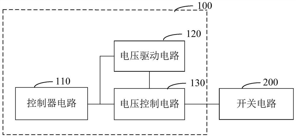
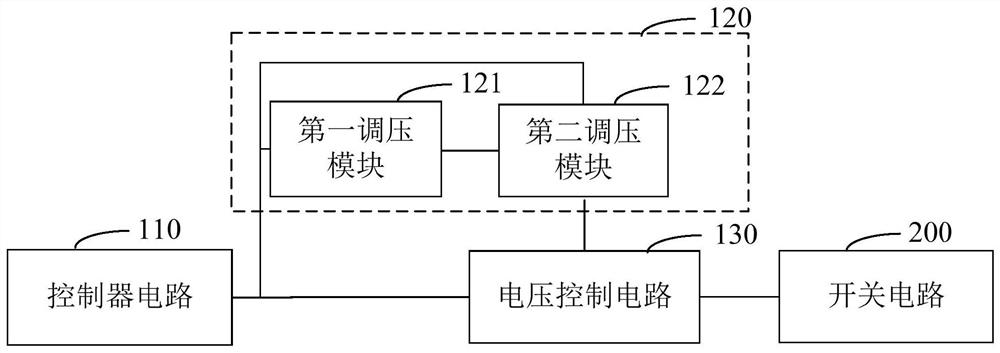
The invention relates to a control circuit, a charging circuit and electronic equipment. The control circuit comprises a controller circuit, a voltage driving circuit and a voltage control circuit, wherein the driving end of the controller circuit controls the output of a driving signal; when the voltage driving circuit and the voltage control circuit receive the driving signal, the voltage driving circuit adjusts a first power supply voltage into a driving voltage according to the driving signal, and the voltage control circuit controls a switching circuit to be switched on according to the driving voltage; and when the voltage driving circuit and the voltage control circuit do not receive the driving signal, the voltage driving circuit outputs a first power supply voltage, and the voltage control circuit controls the switching circuit to be switched off according to the first power supply voltage. Therefore, as one port of the controller circuit is matched with the voltage driving circuit and the voltage control circuit, the on state and the off state of the switching circuit are controlled, so port resources of the controller circuit can be effectively saved and cost is reduced.

Description

technical field [0001] The present application relates to the technical field, in particular to a control circuit, a charging circuit and electronic equipment. Background technique [0002] Switch tubes are widely used in charging systems for switching charging, state switching and safety protection. The switching tube may be an NMOS (N-Metal-Oxide-Semiconductor, N-type Metal-Oxide-Semiconductor) switching tube. In order to ensure the normal operation of the charging system, the controller needs to use two I / O (Input / Output, input / output) ports to complete the on and off states of the NMOS switch tube. For example, when the switch tube needs to be turned off, except One of the I / O ports stops outputting signals, and another I / O port is required to pull down the gate voltage of the NMOS switch to avoid device burnout due to incomplete shutdown of the NMOS switch. [0003] However, the I / O port resources of the controller are very precious. Usually, multiple I / O ports are re...

Claims


Application Information

Patent Timeline
IPC IPC(8): H02J7/00
CPCH02J7/007H02J7/00711
Inventor 江森龙
Owner GUANGDONG OPPO MOBILE TELECOMM CORP LTD
Why Eureka
Try Eureka