
Conveyor belt energy recovery equipment

A technology of energy recovery and conveyor belt, which is applied in the direction of controlling mechanical energy, casing/cover/support, electrical components, etc., can solve problems such as unusable, material loss, and failure to achieve flameproofing, and achieve the effect of improving safety

Active Publication Date: 2021-07-23
包头市国安工程机械有限公司
View PDF15 Cites 0 Cited by
  • Summary
  • Abstract
  • Description
  • Claims
  • Application Information

AI Technical Summary

Problems solved by technology

Speed ​​regulation is essential in the process of transporting materials by the conveyor belt. The traditional mechanism deceleration methods are all mechanical or hydraulic pressure braking modes. The kinetic energy is converted into heat energy through the braking mechanism and consumed. At the same time, the friction surface of the mechanism correspondingly has a certain amount of material loss.
[0003]In the related technology, a kind of gravity potential energy recovery power generation device of the mineral material conveyor belt is proposed, and the energy recovery and current conversion of the conveyor belt are realized by installing the power generation roller and the inverter However, the inventors of the present application found that this related technology cannot achieve the effect of flameproof, so it cannot be used in hazardous places with explosive gas

Method used


Image

  • Conveyor belt energy recovery equipment

Examples


Embodiment Construction

[0026] Embodiments of the invention are described in detail below, examples of which are illustrated in the accompanying drawings. The embodiments described below by referring to the figures are exemplary and are intended to explain the present invention and should not be construed as limiting the present invention.

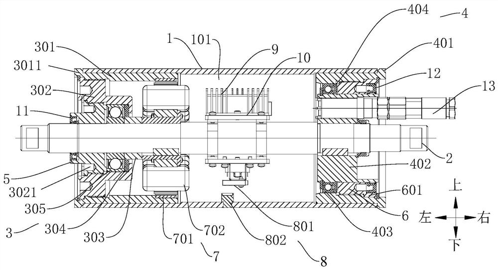
[0027] The conveyor belt energy recovery device according to the embodiment of the present invention includes a roller 1, a support shaft 2, a first flameproof assembly 3, a second flameproof assembly 4, a first seal seat 5, a second seal seat 6, a power generation assembly 7 and a rotating speed Detection component 8.

[0028] In the roller 1, there is an axial direction along the roller 1 (such as figure 1 Shown in the left and right direction) through the cavity 101, the cavity 101 has the opposite first end in the axial direction of the roller 1 (such as figure 1 The left end of roller 1 shown in ) and the second end (as shown in figure 1 right end of roll...


PUM


Abstract

The invention relates to the technical field of belt conveying, in particular to conveyor belt energy recovery equipment which comprises a roller, a supporting shaft, a first explosive-proof assembly, a second explosive-proof assembly, a first sealing seat, a second sealing seat, a power generation assembly and a rotating speed detection assembly. A cavity is formed in the roller, and the cavity is provided with a first end and a second end. The supporting shaft is used for supporting the roller. The first explosion-proof assembly is arranged at the first end of the cavity, and the second explosion-proof assembly is arranged at the second end of the cavity. The first sealing seat is used for sealing the first end of the cavity, and the second sealing seat is used for sealing the second end of the cavity. The power generation assembly is arranged in the cavity and comprises a permanent magnet ring, a stator core and a stator coil wound on the stator core. The stator core sleeves the supporting shaft. The permanent magnet ring can rotate along with the roller. The rotating speed detection assembly is arranged in the cavity and used for detecting the rotating speed of the roller. According to the conveyor belt energy recovery equipment, energy recovery of a conveyor belt can be achieved, an explosion-proof effect can be achieved, and the operation safety of the equipment is improved.

Description

technical field [0001] The invention relates to the technical field of belt conveying, in particular to a conveyor belt energy recovery device. Background technique [0002] Conveyor belt conveyors are widely used in coal, mining, port, metallurgy, manufacturing and other industries. Speed ​​regulation is essential in the process of transporting materials by the conveyor belt. The traditional mechanism deceleration methods are all mechanical or hydraulic pressure braking modes. The kinetic energy is converted into heat energy through the braking mechanism and consumed. At the same time, the friction surface of the mechanism correspondingly has a certain amount of material loss. . [0003] In the related technology, a gravity potential energy recovery power generation device for the mineral material conveyor belt is proposed, and the energy recovery and current conversion of the conveyor belt are realized by installing the power generation roller and the inverter. However, t...

Claims


Application Information

Patent Timeline
Patent Type & Authority Applications(China)
IPC IPC(8): H02K7/18H02K5/136H02K5/16H02K5/10H02K11/21
CPCH02K7/1807H02K5/136H02K5/163H02K5/10H02K11/21Y02P70/10
Inventor 赵守国
Owner 包头市国安工程机械有限公司
Learn More