Microwave ablation needle
A technology of microwave ablation and bevel teeth, applied in the field of microwave ablation needles, can solve the problem of single function of ultrasonic microwave ablation needles, etc., and achieve the effects of realizing elastic compensation and realizing displacement compensation
- Summary
- Abstract
- Description
- Claims
- Application Information
AI Technical Summary
Problems solved by technology
Method used
Image
Examples
specific Embodiment approach 1
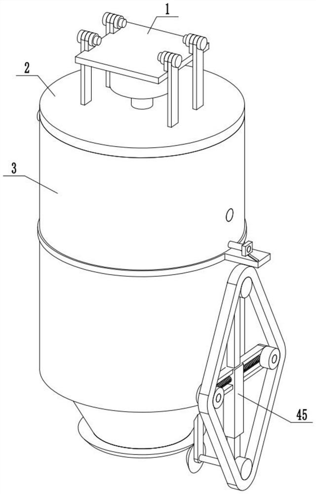
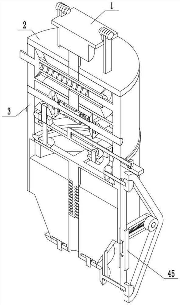
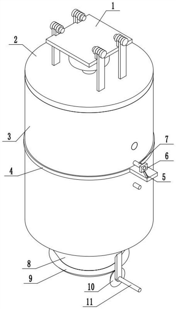
[0033] Combine below Figure 1-11 Describe this embodiment, a microwave ablation needle, including an outer frame assembly, a reversing assembly, a power clutch assembly, a length extension assembly, a switching assembly, and a tensioning assembly 45, the reversing assembly is connected to the outer frame assembly, and the power clutch The assembly is connected with the outer frame assembly, the length expansion assembly is connected with the outer frame assembly, the switching assembly is connected with the outer frame assembly, and the tensioning assembly 45 is connected with the outer frame assembly.
specific Embodiment approach 2
[0035] Combine below Figure 1-11Describe this embodiment, this embodiment will further explain the first embodiment, the outer frame assembly includes the input motor 1, the upper end cover 2, the extended outer frame 3, the second bevel gear 14, the third bevel gear 19, the bevel gear shaft A20, the bevel gear Gear 5 21, bevel gear 8 27, bevel gear shaft 2 28, drive straight gear 1 29, inner end ring gear 1 30, inner end ring gear 2 31, inner end ring gear 3 35, bevel gear shaft 5 39, bevel gear Thirteen 40, the input motor 1 is fixedly connected to the upper end cover 2, the upper end cover 2 is fixedly connected to the expansion frame 3, the bevel gear 2 14 is fixedly connected to the output shaft of the input motor 1, and the output shaft of the input motor 1 is connected through a bearing On the upper end cover 2, the bevel gear three 19 is fixedly connected with the bevel gear shaft A20, the bevel gear shaft A20 is rotatably connected with the extended outer frame 3, th...
specific Embodiment approach 3
[0037] Combine below Figure 1-11 Describe this embodiment, this embodiment will further explain Embodiment 1, the reversing assembly includes bevel teeth 6 22, bevel teeth 7 23, middle end shaft 24, matching sleeve 25, drive sleeve 26, bevel teeth 14 44. Driving boss 1 46, driving boss 2 47, the middle shaft 24 is rotationally connected with the expansion frame 3, bevel teeth 14 44 are fixedly connected with the middle shaft 24, bevel teeth 6 22, bevel teeth 7 23 Both are rotatably connected with the middle shaft 24, the bevel teeth 6 22 and bevel teeth 7 23 are both rotatably connected with the expansion frame 3, the matching sleeve 25 is slidably connected with the middle shaft 24, and the driving sleeve 26 is rotatably connected with the matching sleeve 25 , the driving sleeve 26 is slidingly connected with the expansion frame 3, the first driving boss 46 is fixedly connected with the sixth bevel tooth 22, the seventh bevel tooth 23 is fixedly connected with the second dri...
PUM
 Abstract
Description
Claims
Application Information
 - R&D Engineer
- R&D Manager
- IP Professional
- Industry Leading Data Capabilities
- Powerful AI technology
- Patent DNA Extraction
Browse by: Latest US Patents, China's latest patents, Technical Efficacy Thesaurus, Application Domain, Technology Topic, Popular Technical Reports.
© 2024 PatSnap. All rights reserved.Legal|Privacy policy|Modern Slavery Act Transparency Statement|Sitemap|About US| Contact US: help@patsnap.com


