Heat dissipation device for new energy charging pile and heat dissipation method

A heat dissipation device and charging pile technology, applied in charging stations, electric vehicle charging technology, electric vehicles, etc., can solve problems such as poor practicability, damage to electrical components, and limited detection range, and achieve reasonable structure, avoid damage, and wide detection range Effect

Inactive Publication Date: 2021-07-27
黄小林
View PDF0 Cites 3 Cited by
  • Summary
  • Abstract
  • Description
  • Claims
  • Application Information

AI Technical Summary

Problems solved by technology

[0003] Most of the existing cooling devices for charging piles use temperature sensors to internally detect the temperature, and then control the cooling fan to dissipate heat and cool down. However, the temperature sensors are generally fixed, resulting in a limited detection range. The heat emitted by electrical components is different. When the temperature sensor detects high temperature, some electrical components may be damaged due to overheating, and the practicability is poor. Therefore, this application discloses a new energy charging pile. Heat dissipation device and heat dissipation method to meet the demand

Method used


Image

  • Heat dissipation device for new energy charging pile and heat dissipation method
  • Heat dissipation device for new energy charging pile and heat dissipation method
  • Heat dissipation device for new energy charging pile and heat dissipation method

Examples


Embodiment

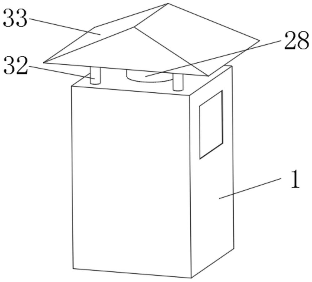
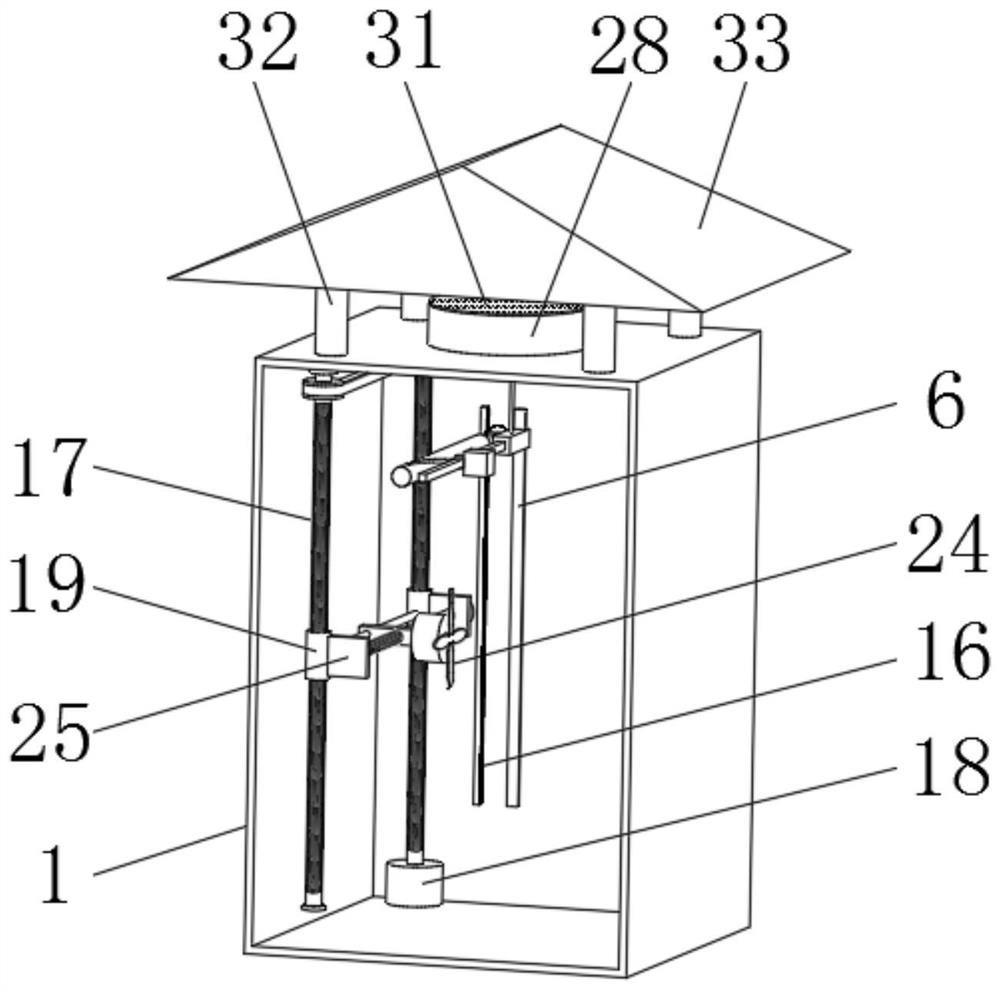
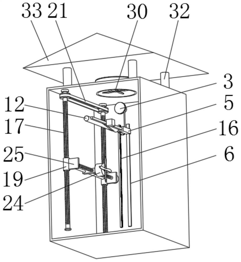
[0042] Example: such as Figure 1-8 The heat dissipation device for a new energy charging pile shown includes a charging pile body 1, a temperature sensor 9 is installed in the charging pile body 1 through an up and down reciprocating component and a horizontal reciprocating unit, and a cooling fan 24 is arranged in the charging pile body 1 to dissipate heat. The fan 24 is equipped with a horizontal adjustment assembly, and the horizontal adjustment assembly is connected with a vertical adjustment assembly. The vertical adjustment assembly is connected to the inner wall of the charging pile body 1. The temperature sensor 9 and the cooling fan 24 are located on different vertical surfaces. The temperature sensor 9 It is connected with the vertical adjustment assembly and the horizontal adjustment assembly.

[0043] With the above-mentioned structure, through the setting of the up and down reciprocating components, the horizontal reciprocating unit, and the temperature sensor 9,...


PUM


Abstract

The invention discloses a heat dissipation device for a new energy charging pile and a heat dissipation method, and relates to the technical field of new energy charging piles. The heat dissipation device comprises a charging pile body, wherein a temperature sensor is installed in the charging pile body through an up-down reciprocating assembly and a horizontal reciprocating unit, a cooling fan is arranged in the charging pile body, and a horizontal adjusting assembly is installed on the cooling fan. The invention further discloses a heat dissipation method of the heat dissipation device for the new energy charging pile. Through the arrangement of the up-down reciprocating assembly, the horizontal reciprocating unit and the temperature sensor, comprehensive temperature detection processing can be conducted on the electric appliance elements in the charging pile body, the detection range is wide, the detection is more accurate, and when it is detected that the temperature of local electric appliance elements is high, the cooling fan can be adjusted and moved to a designated position through the vertical adjusting assembly and the horizontal adjusting assembly, the purpose of fixed-point air blowing and heat dissipation is achieved, and the phenomenon that local electric appliance elements are damaged due to too high temperature is avoided.

Description

technical field [0001] The invention relates to the technical field of new energy charging piles, in particular to a heat dissipation device and a heat dissipation method for new energy charging piles. Background technique [0002] The function of the charging pile is similar to the refueling machine in the gas station. It can be fixed on the ground or wall, and installed in the parking lot or charging station of public buildings and residential areas. It can charge various types of electric vehicles according to different voltage levels. When the charging pile is running, its internal electrical components will generate a lot of heat, so it is necessary to use a heat sink to cool down. [0003] Most of the existing cooling devices for charging piles use temperature sensors to internally detect the temperature, and then control the cooling fan to dissipate heat and cool down. However, the temperature sensors are generally fixed, resulting in a limited detection range. The h...

Claims


Application Information

Patent Timeline
Patent Type & Authority Applications(China)
IPC IPC(8): B60L53/302B60L53/31B65H75/38B65H75/44
CPCB65H75/38B65H75/44B60L53/302B60L53/31Y02T10/70Y02T10/7072Y02T90/12
Inventor 黄小林
Owner 黄小林
Why Eureka
Try Eureka