Stereoscopic warehouse type temporary storage machine

A technology of three-dimensional warehouse type and temporary storage machine, which is applied in the field of machinery, can solve the problems of not meeting the processing efficiency of equipment, affecting the matching of intelligent equipment, and requiring high precision, so as to improve the ability to adapt to efficient intelligent production lines and increase the quantity , The effect of smooth plate transfer

Pending Publication Date: 2021-07-27
咸宁市诺贝佳机电设备有限公司
View PDF0 Cites 1 Cited by
  • Summary
  • Abstract
  • Description
  • Claims
  • Application Information

AI Technical Summary

Problems solved by technology

[0003] The temporary storage machine includes a pallet input rack, a pallet discharge rack and multiple temporary storage racks between them. With the advancement of intelligent production, the production efficiency of each process has been greatly improved. The existing temporary storage Because each temporary storage rack needs to be equipped with a separate power mechanism, the number of temporary storage racks in one temporary storage machine will not be too many. The existing ones are generally 20 layers, and the plates enter the temporary storage rack or are output from the temporary storage rack. At the same time, it is necessary to control the corresponding temporary storage rack to start its power. The disadvantages of this method are: 1. The control of a certain temporary storage rack needs to obtain the position information of the corresponding incoming or outgoing rack, and then start and enter the rack. Or the action of the temporary storage rack for the leveling of the pallet rack, so that the boards can enter the temporary storage rack from the incoming rack or output from the temporary storage rack to the outgoing pallet rack. The control is complicated and the failure rate is high; 2. Each temporary storage rack is It is necessary to set up a separate power system. The existence of the power system of each temporary storage rack makes the layer height of the adjacent temporary storage racks larger, and the number of temporary storage racks of the temporary storage machine is limited, which cannot meet the increasing processing of each equipment. Efficiency affects the matching of intelligent equipment; 3. The movement of the temporary storage rack needs to be coordinated with the loading and unloading racks, and the accuracy of controlling the movement of the temporary storage rack is high, which is likely to cause failures such as "stuck" ; 4. When the front and back processes are not synchronized, especially when there is refueling or short-term shutdown in the front or rear processes, it is difficult for the existing temporary storage machine to achieve "first in first out", "last in first out" and "straight through in and out". Combination of three functions; in a word: because the temporary storage racks of the existing temporary storage machine are controlled by independent power devices, they cannot be automatically and efficiently coordinated with the incoming or outgoing racks. It is difficult to match the incoming and outgoing pallets when the board enters the temporary storage rack or the board is discharged from the temporary storage rack, which limits the function, efficiency and high failure rate of the temporary storage machine

Method used


Image

  • Stereoscopic warehouse type temporary storage machine
  • Stereoscopic warehouse type temporary storage machine
  • Stereoscopic warehouse type temporary storage machine

Examples


Embodiment Construction

[0037] The following are specific embodiments of the present invention and in conjunction with the accompanying drawings, the technical solutions of the present invention are further described, but the present invention is not limited to these embodiments.

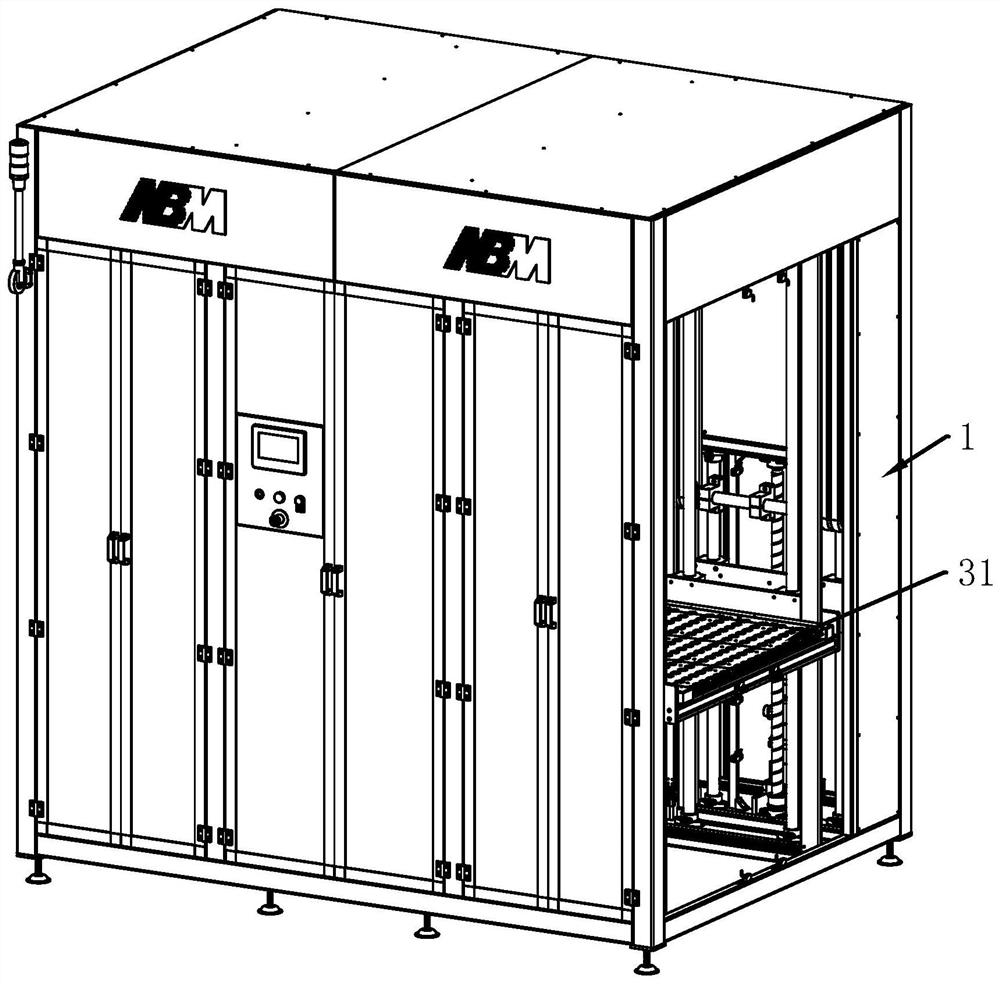
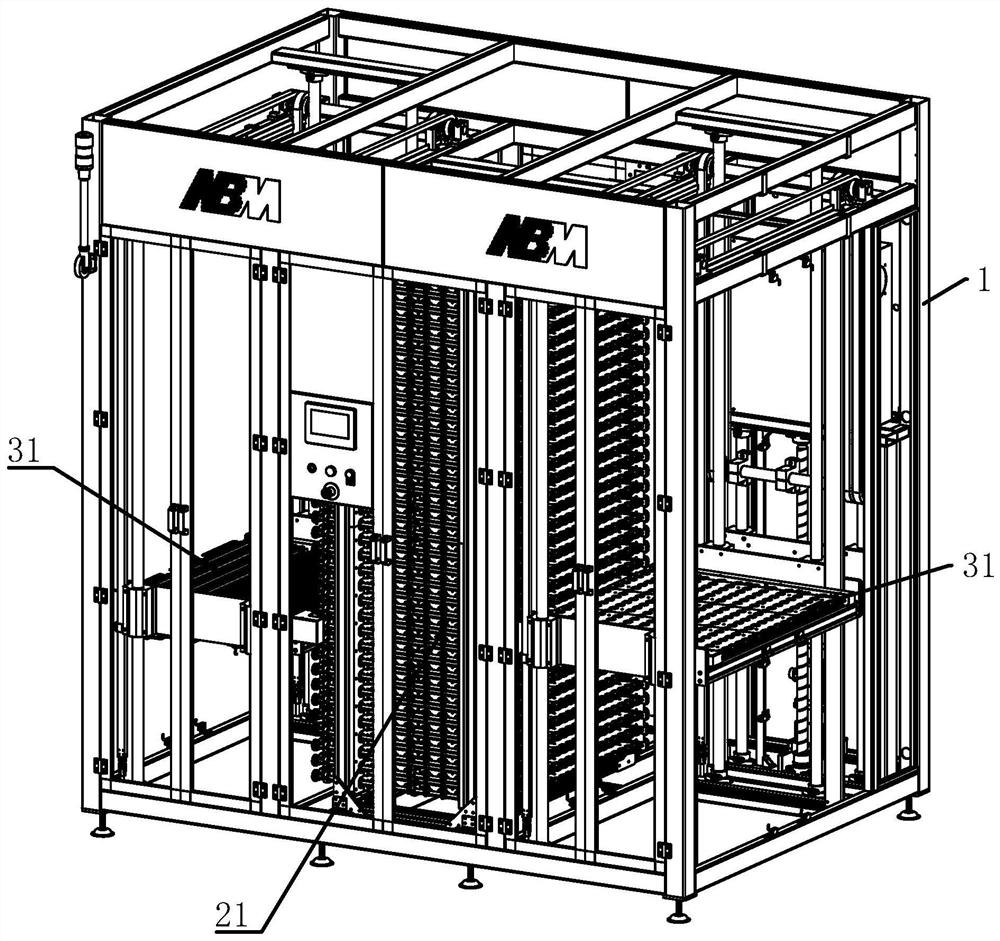
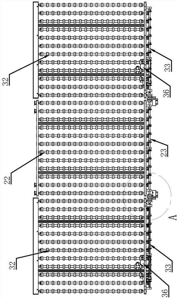
[0038] Such as Figure 1 to Figure 7 As shown, it includes a frame 1, two plate feeding mechanisms and a temporary storage mechanism. The temporary storage mechanism is located between the two plate feeding mechanisms. The temporary storage mechanism includes several temporary storage racks 21 vertically arranged on the frame 1 alternately. The temporary storage rack 21 is provided with a number of first conveying rollers 22 which are rotatably connected to the frame 1 and a first transmission roller 23 which is rotatably connected to the frame 1. The first conveying roller 22 is fixedly provided with a first passive The bevel teeth 24, the first drive roller 23 are fixedly provided with several first active bevel teeth 25...


PUM


Abstract

The invention provides a stereoscopic warehouse type temporary storage machine, and belongs to the technical field of machinery. The temporary storage machine comprises a rack, two plate conveying mechanisms and a temporary storage mechanism, wherein the temporary storage mechanism is located between the two plate conveying mechanisms, and comprises a plurality of temporary storage racks longitudinally arranged on the rack at intervals; a plurality of first conveying rollers rotatably connected to the rack, and a first transmission roller rotatably connected to the rack are arranged on the temporary storage racks; each plate conveying mechanism comprises a plate conveying rack longitudinally connected to the rack slidably, and a plurality of second conveying rollers and a second transmission roller corresponding to the first transmission roller are rotatably connected to the plate conveying rack, and a servo motor for driving the second transmission roller to rotate is arranged on the plate conveying rack; and a non-contact clutch mechanism is arranged between the first transmission roller and the second transmission roller. The temporary storage machine has the advantages that plates can be switched between the plate conveying mechanism and the temporary storage mechanism and the like.

Description

technical field [0001] The invention belongs to the technical field of machinery, and relates to a three-dimensional bin-type temporary storage machine. Background technique [0002] In the PCB board processing production line, a temporary storage machine is generally set up between the two processes to ensure that the rear process does not affect the continuity of the front process. If the equipment corresponding to the rear process fails, the front process does not need to stop. When the plate speed is inconsistent with the plate output speed of the previous process, the continuous progress of the two processes can also be realized through the temporary storage machine; the temporary storage machine is to temporarily store the plates that have been produced or are to be imported in a certain process of connection, so that they can be processed in a certain process. Provide timely supply when the process needs it. [0003] The temporary storage machine includes a pallet in...

Claims


Application Information

Patent Timeline
IPC IPC(8): B65G1/10
CPCB65G1/10
Inventor 吴当刘明俊
Owner 咸宁市诺贝佳机电设备有限公司
Why Eureka
Try Eureka