Waterproof structure for thin part at junction of steel latticed column and foundation slab and treatment method

A technology of steel lattice columns and foundation floor, which is applied in basic structure engineering, underwater structures, water conservancy projects, etc., can solve problems such as leakage around lattice columns, and achieve construction quality assurance, simple implementation, and structural simple effect

Active Publication Date: 2021-07-27
CHINA MCC17 GRP
View PDF7 Cites 0 Cited by
  • Summary
  • Abstract
  • Description
  • Claims
  • Application Information

AI Technical Summary

Problems solved by technology

[0002] Most of the support in the foundation pit can only be removed after the construction of the basement or the construction of the basement floor is completed, and the corresponding support replacement requirements are met. During the construction of the floor, the steel lattice support columns need to be partly poured into the concrete components. If the treatment is not in place, Circumstances that may cause leakage around lattice columns in the future

Method used


Image

  • Waterproof structure for thin part at junction of steel latticed column and foundation slab and treatment method
  • Waterproof structure for thin part at junction of steel latticed column and foundation slab and treatment method
  • Waterproof structure for thin part at junction of steel latticed column and foundation slab and treatment method

Examples


Embodiment 1

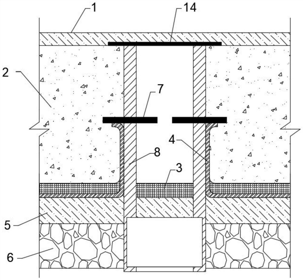
[0044] Such as Figure 1 to Figure 2 As shown, a detailed waterproof structure at the junction of a steel lattice column and a foundation floor, including a steel lattice column 8, including a building surface layer 1, a foundation floor layer 2, a waterproof protection layer 3, and a waterproof layer arranged in sequence from top to bottom 14. The concrete cushion 5 and the foundation 6, the top of the steel lattice column 8 is provided with a waterproof layer 2 14 and the lower surface of the waterproof layer 14 is flush with the building surface 1, and the upper surface of the steel lattice column 8 A water-stop flange 7 is provided, and the side of the waterproof layer 4 away from the waterproof protective layer 3 extends to the lower surface of the water-stop flange 7 and is bonded to each other, and the side wall of the waterproof layer 4 is connected to the steel lattice structure. Column 8 sidewalls are bonded. The periphery of the steel lattice column 1 is waterproof...

Embodiment 2

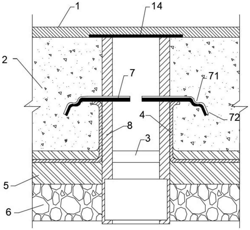
[0046] Such as image 3 As shown, on the basis of Example 1, the water-stop flange 7 is further improved on the waterproof effect, specifically: the water-stop flange 7 is located in the middle of the base floor layer 2, and the water-stop flange The component 7 includes a fixed part 71 , a water stop part 1 72 and a water stop part 2 73 integrally connected. Utilizing the design at the special position of the water-stop flange 7 can effectively ensure its construction efficiency and feasibility.

[0047]In a further preferred solution of this embodiment, the water stop part 1 72 and the fixed part 71 are set at an obtuse angle, and the angle between the water stop part 2 73 and the water stop part 1 72 is smaller than the water stop part 1 72 and the fixed part The angle between 71. The inclination angle of the water stop part 1 72 and the water stop part 71 is used to ensure its waterproof effect and achieve a double waterproof effect.

[0048] In a further preferred solu...

Embodiment 3

[0050] Such as image 3 As shown, a method for processing the detailed waterproof structure at the junction of the steel lattice column and the foundation floor includes the following steps:

[0051] First, select the water-stop flange 7, the main material of the steel lattice column 8 with a military width of each side is not less than 100mm, and the thickness is not less than 10mm, and then double-sided embroidery;

[0052] Secondly, double-sided welding is performed on the water-stop flange 7 and the steel lattice column 8, the height of the weld is not less than 8mm, and the anti-rust paint is painted on both sides, and the welding position is the center of the thickness of the foundation floor;

[0053] Thirdly, construct the concrete cushion layer 5, make connections around the steel lattice columns 8 and make arc angles;

[0054] Subsequently, the waterproof coiled material is finally constructed between the concrete cushion 5 and the steel lattice column 8 to make a w...


PUM


Abstract

The invention discloses a waterproof structure for a thin part at the junction of a steel latticed column and a foundation slab and a treatment method, and belongs to the field of building construction. The waterproof structure comprises a steel latticed column; the waterproof structure further comprises a building surface layer, a foundation slab layer, a waterproof protection layer, a first waterproof layer, a concrete cushion layer and a foundation which are sequentially arranged from top to bottom; a second waterproof layer is arranged at the top of the steel latticed column, and the lower surface of the second waterproof layer is flush with the building surface layer; a water stop flange piece is arranged on the steel latticed column; the side, away from the waterproof protection layer, of the first waterproof layer extends to the lower surface of the water stop flange piece and adheres to the water stop flange piece; and the side wall of the first waterproof layer adheres to the side wall of the steel latticed column. The periphery of the steel latticed column is subjected to waterproof treatment through the water stop flange piece, then the side portion of the steel latticed column is subjected to waterproof treatment through the first waterproof layer on the side wall and on the concrete cushion layer, the top of the steel latticed column is treated through the second waterproof layer, and therefore the overall anti-seepage effect is good, implementation is simple and easy, the overall structure is firm, and wide application is facilitated.

Description

technical field [0001] The invention relates to the technical field of building construction, in particular to a detailed waterproof structure at the junction of a steel lattice column and a foundation floor and a treatment method. Background technique [0002] Most of the support in the foundation pit can only be removed after the construction of the basement or the construction of the basement floor is completed, and the corresponding support replacement requirements are met. During the construction of the floor, the steel lattice support columns need to be partly poured into the concrete components. If the treatment is not in place, In the future, it may cause leakage around the lattice column. This problem must be effectively solved in order to ensure the stability of the foundation pit support system, meet the use conditions of the foundation pit without affecting the normal construction of the main structure, and ensure the smooth realization of the schedule. Content...

Claims


Application Information

Patent Timeline
Patent Type & Authority Applications(China)
IPC IPC(8): E02D29/16E02D31/02
CPCE02D29/16E02D31/02E02D31/025
Inventor 张璋邹东浩
Owner CHINA MCC17 GRP
Why Eureka
Try Eureka