
Optical free-form surface full-aperture detection method based on multi-error real-time compensation

A real-time compensation, multi-error technology, applied in the field of full-aperture detection of large-diameter optical free-form surfaces, can solve problems such as damage, and achieve the effect of ensuring measurement efficiency, improving measurement accuracy, and solving high-precision detection of surface errors.

Active Publication Date: 2021-07-27
LASER FUSION RES CENT CHINA ACAD OF ENG PHYSICS
View PDF18 Cites 1 Cited by
  • Summary
  • Abstract
  • Description
  • Claims
  • Application Information

AI Technical Summary

Problems solved by technology

[0006] In view of this, the present invention provides a large-aperture optical free-form surface full-aperture detection method based on multi-error real-time compensation, which avoids damage to the component surface during the measurement process, and compensates the measurement motion error in real time, and removes it through the post-data processing algorithm. Measure the motion error, improve the measurement accuracy, and solve the problem of high-precision detection of surface error in the ultra-precision manufacturing process of large-aperture free-form optical components

Method used


Image

  • Optical free-form surface full-aperture detection method based on multi-error real-time compensation
  • Optical free-form surface full-aperture detection method based on multi-error real-time compensation
  • Optical free-form surface full-aperture detection method based on multi-error real-time compensation

Examples


Embodiment Construction

[0056] The following will clearly and completely describe the technical solutions in the embodiments of the present invention with reference to the accompanying drawings in the embodiments of the present invention. Obviously, the described embodiments are only some, not all, embodiments of the present invention. Based on the embodiments of the present invention, all other embodiments obtained by persons of ordinary skill in the art without making creative efforts belong to the protection scope of the present invention.

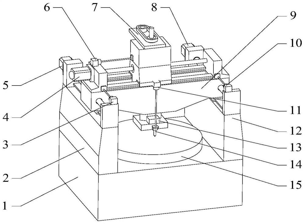
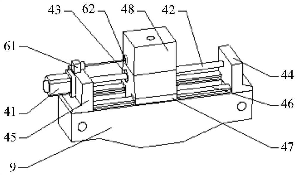
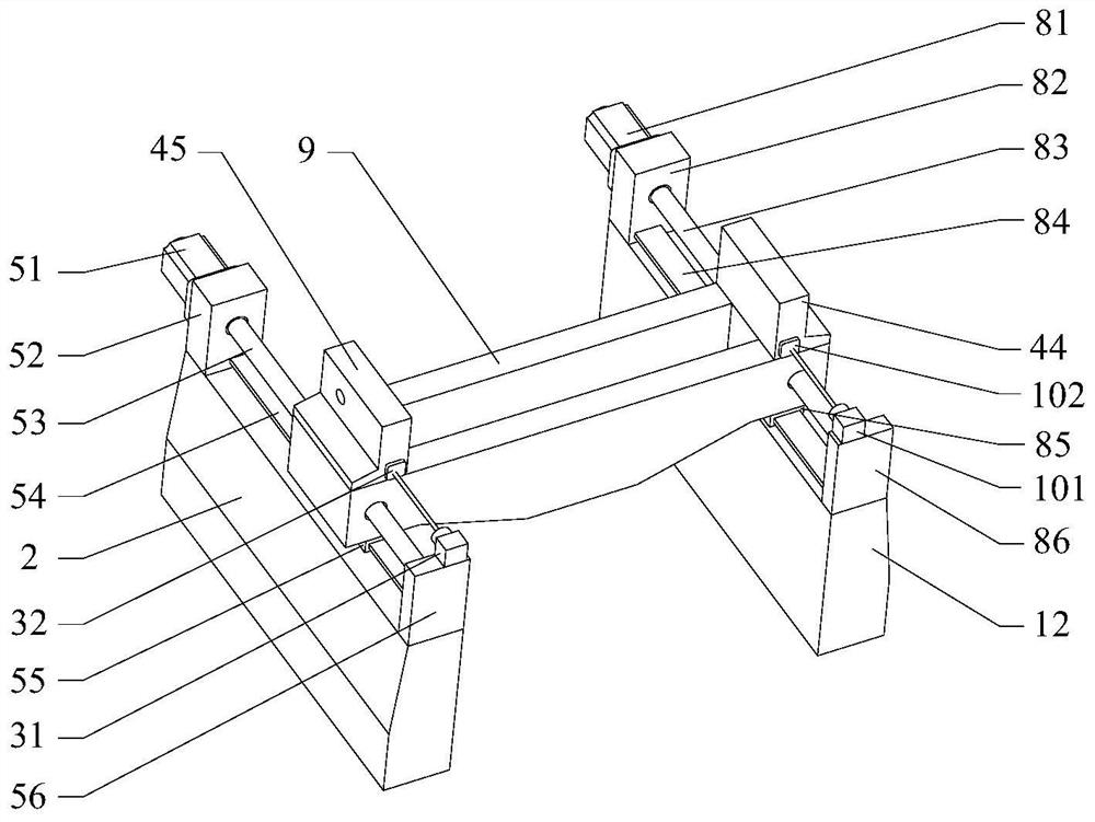
[0057] The first aspect of this embodiment discloses a full-aperture detection of a large-aperture optical free-form surface based on multiple error real-time compensation, see figure 1 , a schematic diagram of the overall structure of the large-aperture optical free-form surface full-aperture detection device based on multi-error real-time compensation is given.

[0058] Used to detect free-form surface optical components, including X-axis motion execution sy...


PUM


Abstract

The invention provides a large-aperture optical free-form surface full-aperture detection device and method based on multi-error real-time compensation, and the detection device is used for detecting a free-form surface optical element, and comprises an X-axis motion execution system, a Y-axis motion execution system and a Z-axis motion execution system; a Y-axis position measurement system is used for measuring the position of the X-axis motion execution system on the Y axis; an X-axis position measurement system is used for measuring the position of the Z-axis motion execution system on the X axis; a double-axis tilt angle sensor is used for detecting space attitude variation of a non-contact displacement measuring head in an XZ plane and a YZ plane when the non-contact displacement measuring head moves along the X axis and the Y axis, and a Z-axis position measurement system is used for measuring the position of the non-contact displacement measuring head on the Z axis; and the non-contact displacement measuring head performs scanning motion along the surface of the free-form surface optical element. Damage to the surface of the element in the measurement process is avoided, the measurement motion error is compensated in real time, and the surface shape error measurement precision of the large-aperture free-form surface optical element is improved.

Description

technical field [0001] The invention relates to the technical field of optical ultra-precision machining, in particular to a full-aperture detection method for large-aperture optical free-form surfaces based on multi-error real-time compensation. Background technique [0002] Compared with traditional spherical optical elements, free-form optical elements (such as off-axis aspheric surfaces) have many superior performances in terms of optical performance, safety and space, weight limitation, etc., and have been widely used in modern large-scale ultra-precision optical systems. Due to the non-rotational symmetry of the free-form surface optical element, ultra-precision grinding is generally used to realize the precision forming process of the element. Grinding and forming processing accuracy is a key technical index that affects the efficiency and precision of subsequent polishing of components and the final performance of components. The high-precision detection of the surf...

Claims


Application Information

Patent Timeline
Patent Type & Authority Applications(China)
IPC IPC(8): G01B11/24G01M11/02
CPCG01B11/24G01M11/025
Inventor 周炼赵世杰郑楠韦前才李洁陈贤华张清华王健许乔
Owner LASER FUSION RES CENT CHINA ACAD OF ENG PHYSICS
Learn More