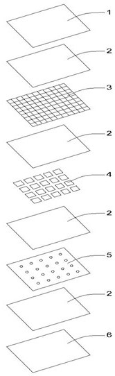
[0003] At present, photovoltaic modules mainly include rigid packaging and flexible packaging. The so-called rigid photovoltaic module is mainly composed of tempered glass,
adhesive layer and back sheet to
package the solar photovoltaic
cell chip in a sandwich-like structure, plus an aluminum
alloy frame and a
junction box. Rigid photovoltaic modules are formed. Rigid photovoltaic modules are safe and reliable, but the rigid modules are bulky, and the tempered glass on the surface is fragile and easy to break, and it is not easy to carry. It causes great inconvenience when used in camping, tents, etc. It is generally used for fixed power stations on the ground; The so-called flexible packaged photovoltaic modules are mainly thin-film solar photovoltaic cells prepared on flexible material substrates (stainless steel,
polymer, etc.), and then packaged in a sandwich structure using flexible materials to form flexible photovoltaic modules. Features are light weight, thin, rollable and suitable for folding and carrying, suitable for use in camping, tents and other occasions
[0004] In order to have the advantages of light weight of flexible components and overcome the problem of low conversion efficiency of thin-film photovoltaic cells in flexible components, there are many kinds of semi-flexible lightweight photovoltaic components packaged with
crystalline silicon solar cells in the military and civilian markets. The product features are Lighter than rigid photovoltaic modules, bendable,
high energy density, easy to carry, etc., the structure is between rigid photovoltaic modules and flexible photovoltaic modules, and the conversion efficiency is higher than flexible photovoltaic modules. It is very popular in the mobile market and military market. At present, semi-flexible lightweight photovoltaic modules are pursuing the
lightness and softness of solar cells, but at the same time sacrifice the quality of some products, so there are great quality defects. The main reasons for the decline in product quality are: first,
crystalline silicon The battery sheet is getting thinner and more fragile, and the
chip will be cracked and damaged by external force, which may cause hot spots, especially the crystalline
silicon battery has a
high current density, and there is a
potential risk of fire, and this external force exists in the operation. During installation, transportation, handling, and under the
constant load of wind pressure change load and
snow pressure, excessive bending and vibration will cause the
monocrystalline silicon battery chip to form cracks or even break, especially the general structure of semi-flexible photovoltaic modules is the back A carrier plate is added to protect the
monocrystalline silicon battery chip from damage, and the front is packaged with thinner
ETFE and hot-melt
adhesive film in order to improve the
transmittance, often ignoring the damage to the
monocrystalline silicon battery chip due to the
impact stress from the front. For example, the damage of hail, flying sand and rocks leads to the damage of monocrystalline
silicon battery chips, causing hot spots and causing fire risks; second, the influence of
water vapor penetration on the
insulation resistance of the semi-flexible photovoltaic module
system during use will cause the
system to fail to work or cause safety hazards due to electric leakage. Accidents, even caused
lightning strikes and damage to semi-flexible photovoltaic modules. Under the repeated stress of wind load, the material at the fixed point will deform → tear → delaminate under the stress, and
water vapor will enter the interior of the monocrystalline
silicon cell chip along the gap, resulting in
package failure and reduced insulation; (2) Semi-flexible
photovoltaics Modules generally adopt a frameless design. The packaging materials of each layer have been eroded by rain, wind,
snow, salt spray,
ultraviolet rays,
thermal expansion and contraction for a long time, coupled with the damage of changing load stress, semi-flexible photovoltaic modules will begin to split at the edge. layer, causing
water vapor to invade the interior of the crystalline
silicon cell chip from the edge, resulting in package failure and reduced insulation; (3) semi-flexible photovoltaic modules are generally packaged with
polymer materials and hot-melt materials, and the surface packaging material is damaged, resulting in water vapor from The edge or damaged position invades the interior of the crystalline
silicon cell chip, resulting in
insulation failure; (4) The damage caused by the crystalline
silicon cell chip during the use of semi-flexible photovoltaic modules, or the shading of shadows,
bird droppings, leaves, etc. will cause local hot spots, making it The packaging material is aged at a relatively high temperature for a long time →
cracking →
delamination → burnt, reducing insulation
In view of the above problems,
Chinese Patent Publication No.: CN112189264A "A Lightweight and Flexible Photovoltaic Module Comprising a Front Layer Made of a
Polymer and a Back Layer Made of a
Composite Material" provides a
partial solution by adding a
fiber-based prepreg on the backlight surface. Material-type composite materials and additional
layers increase the strength, but they cannot solve the external force damage on the front; thirdly, the current junction boxes of solar photovoltaic modules are traditional junction boxes, which have the following defects: (1) Once the solar photovoltaic module is damaged Or generate hot spots, which can cause the bypass protection
diode inside the
junction box to conduct for a long time and cause overheating, resulting in a potential
fire risk; (2) local damage to photovoltaic modules may lead to a decrease in
insulation resistance and affect the operation of the entire
system. The existing technology can only Replacing solar photovoltaic modules can not repair and use solar photovoltaic modules, resulting in an increase in cost; (3) When the traditional junction box is connected to a string of photovoltaic modules, the string
voltage of the photovoltaic module exceeds the safe
voltage of 36V, or even exceeds 1000V.
Electric shock safety accidents will occur when operating in special occasions; (4) After the traditional junction box is connected to the string, the
voltage exceeds the safe voltage of 36V. Once a fire occurs in the
photovoltaic power station, the photovoltaic array is a
charged body, and firefighters cannot use water to extinguish the fire. Yes, you can only watch the
power station burn down, and even cause a huge safety accident

