A kind of equipment for cutting off the insulation layer of the cable end before the installation of the cable joint

A technology of cable joints and cable ends, which is applied to equipment for dismantling/armoring cables, installation of cables, and installation devices for cables, etc. It can solve the problems that connecting pipes and conductors cannot be tightly fitted, shortening the service life of cables, and affecting the installation of joints, etc. , to achieve successful and stable docking, prevent cutting gaps, and facilitate tight fit

Active Publication Date: 2022-04-19
芜湖市科特电线电缆有限公司
View PDF12 Cites 0 Cited by
  • Summary
  • Abstract
  • Description
  • Claims
  • Application Information

AI Technical Summary

Problems solved by technology

[0004] 1. Usually the insulation layer at the end of the cable is cut manually. When cutting, the incision is easy to be cut irregularly, which makes it inconvenient for the conductor to connect with the connecting pipe successfully, and thus inconvenient for the installation of the joint.
[0005] 2. When cutting, impurities such as dander and dust will be produced. If they are not cleaned up in time, the conductive adhesive will not be able to effectively adhere to the outer surface of the conductor, so that the connecting pipe and the conductor cannot be tightly fitted, which will seriously affect the installation of the joint and shorten the cable. service life
[0006] 3. Before laying, it is necessary to manually unwind the cable. When encountering a hard cable, it is time-consuming and laborious to straighten it. The labor workload of the workers is large, which is not conducive to improving the efficiency of cable laying

Method used


Image

  • A kind of equipment for cutting off the insulation layer of the cable end before the installation of the cable joint
  • A kind of equipment for cutting off the insulation layer of the cable end before the installation of the cable joint
  • A kind of equipment for cutting off the insulation layer of the cable end before the installation of the cable joint

Examples


Embodiment Construction

[0040] The technical solutions of the present invention will be further described below in conjunction with the accompanying drawings and through specific implementation methods.

[0041] Wherein, the accompanying drawings are only for illustrative purposes, showing only schematic diagrams, rather than physical drawings, and should not be construed as limitations on this patent; in order to better illustrate the embodiments of the present invention, some parts of the accompanying drawings will be omitted, Enlarged or reduced, does not represent actual product size.

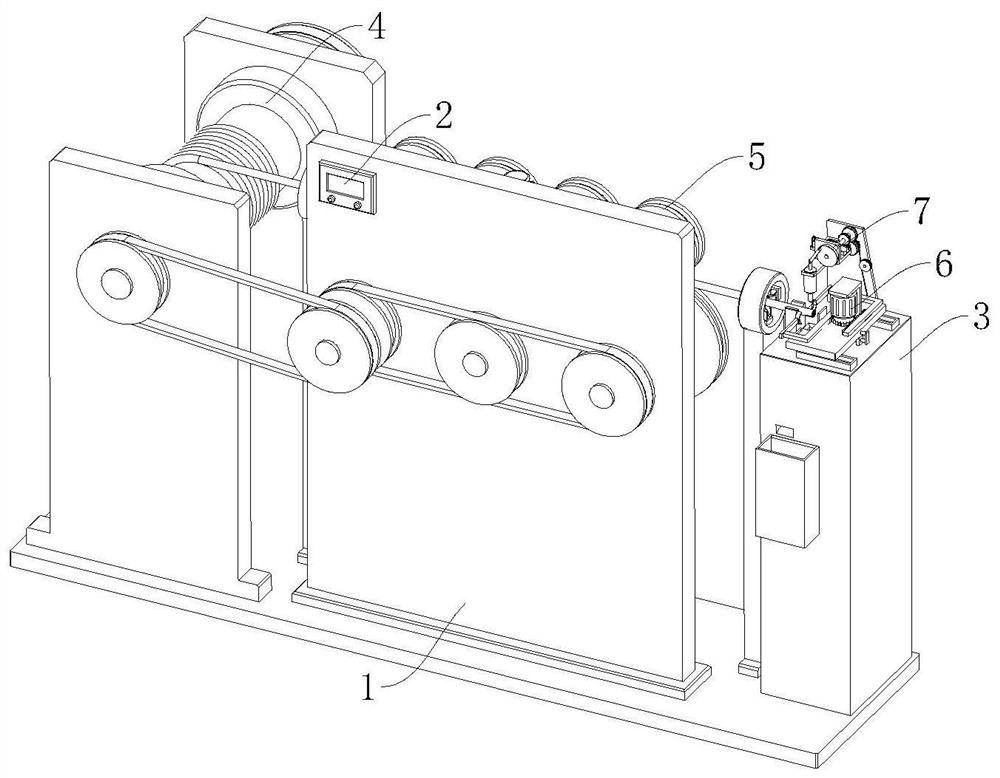
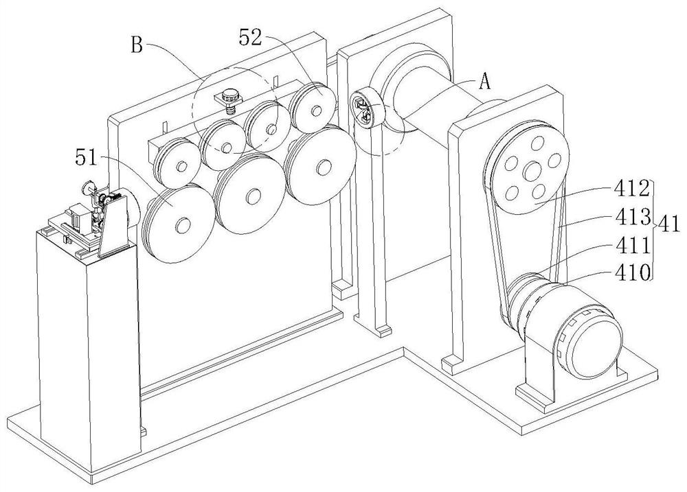
[0042] refer to Figure 1 to Figure 9 The shown one provides a cable end insulation layer removal equipment before the installation of cable joints, including a base and a vertical plate 1, and also includes a controller 2, a processing table 3, an unwinding mechanism 4, a straightening mechanism 5, a cutting mechanism 6 and Cleaning mechanism 7, described controller 2 is fixedly arranged on the outer wall of ver...


PUM


Abstract

The invention relates to the field of cable technology, in particular to a cable end insulation layer removal equipment before installation of cable joints, including a base and a vertical plate, and also includes a controller, a processing table, an unwinding mechanism, a straightening mechanism, a cutting mechanism and a cleaning mechanism. mechanism, unwinding mechanism includes unwinding roller and drive assembly, straightening mechanism includes adjustment assembly, three driving pressure rollers and four driven pressure rollers, cutting mechanism includes tightening assembly, peeling assembly and two semicircular cutters The cleaning mechanism includes a punching bag, an extruding assembly, and a traction assembly. The driving assembly, the tightening assembly, the stripping assembly and the controller are all electrically connected. The present invention relates to a cable end insulation layer cutting device before installation of a cable joint. It can ensure a neat cut and facilitate the installation of joints. At the same time, it has a cleaning function during cutting. It can effectively remove impurities such as dander, facilitate conductor spraying, and ensure that the connecting pipe and conductor are fully fitted, and there is no need for manual unwinding, saving time and effort.

Description

technical field [0001] The invention relates to the technical field of cables, in particular to a device for removing insulation layers at cable ends before installation of cable joints. Background technique [0002] The cable joint is also called the cable head. After the cable is laid, in order to make it a continuous line, each section of the line must be connected as a whole, and these connection points are called cable joints. The cable joints in the middle of the cable line are called intermediate joints, and the cable joints at both ends of the line are called terminal heads. The cable joint is used to lock and fix the incoming and outgoing lines, and play the role of waterproof, dustproof and shockproof. [0003] The installation of existing cable glands has the following deficiencies: [0004] 1. Usually, the insulation layer at the end of the cable is cut manually. When cutting, the cut is easy to be irregular, which makes it inconvenient for the conductor to co...

Claims


Application Information

Patent Timeline
Patent Type & Authority Patents(China)
IPC IPC(8): H02G1/12
CPCH02G1/1258
Inventor 冯林静冯林丽
Owner 芜湖市科特电线电缆有限公司
Why Eureka
Try Eureka