Intelligent set top box with network camera

A network camera, smart set-top box technology, applied in the direction of image communication, selective content distribution, electrical components, etc., can solve the problems of difficult installation and maintenance, cumbersome operation, inconvenience, etc. The effect of high promotion value

Inactive Publication Date: 2021-07-27
湖南省驰维智能科技有限公司
View PDF13 Cites 3 Cited by
  • Summary
  • Abstract
  • Description
  • Claims
  • Application Information

AI Technical Summary

Problems solved by technology

[0003] Commonly used set-top boxes usually have the problem of internal dust deposition during use. The deposited dust will have a greater impact on the performance and service life of the set-top box. However, its structure is fixed. When cleaning the dust, it needs Unplug the connected line, and then disassemble the shell to remove dust. The operation is cumbersome and affects the normal use of the set-top box. The practicability is not high, and there are many internal components, which is inconvenient to install. There are corresponding mounting holes, it is difficult to adjust, which brings inconvenience to installation and maintenance

Method used


Image

  • Intelligent set top box with network camera
  • Intelligent set top box with network camera
  • Intelligent set top box with network camera

Examples


Embodiment 1

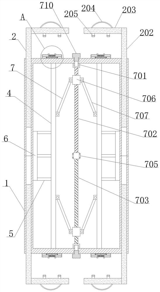
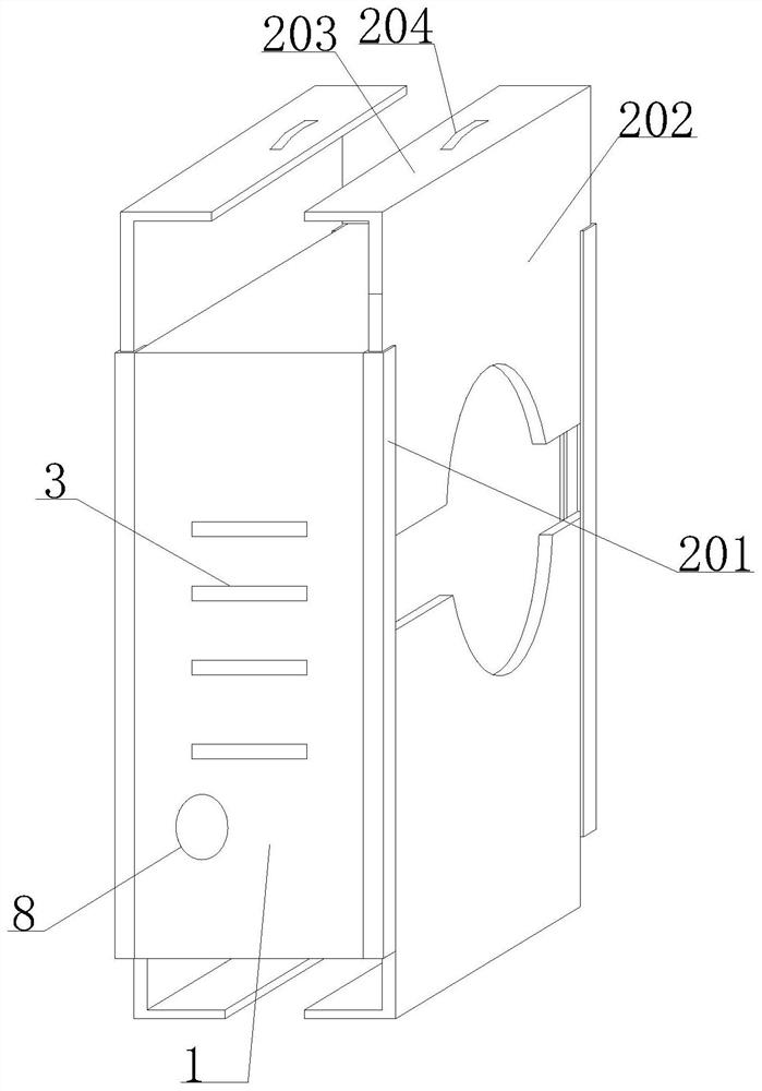
[0029] see Figure 1-7 , the present invention provides a technical solution: a smart set-top box with a network camera, comprising a box body 1, two groups of sliding cover mechanisms 2 are symmetrically arranged on the left and right sides of the box body 1, and the front and back sides of the box body 1 are provided with There are two groups of mounting plates 4 arranged symmetrically inside the box body 1, and a fixing frame 5 is installed on the opposite side of the two groups of mounting plates 4, and a passing plate 6 is installed at the end of the fixing frame 5. An adjustment mechanism 7 is installed inside and on the opposite side of the two sets of mounting plates 4 , and a network camera body 8 is installed on the front of the box body 1 .

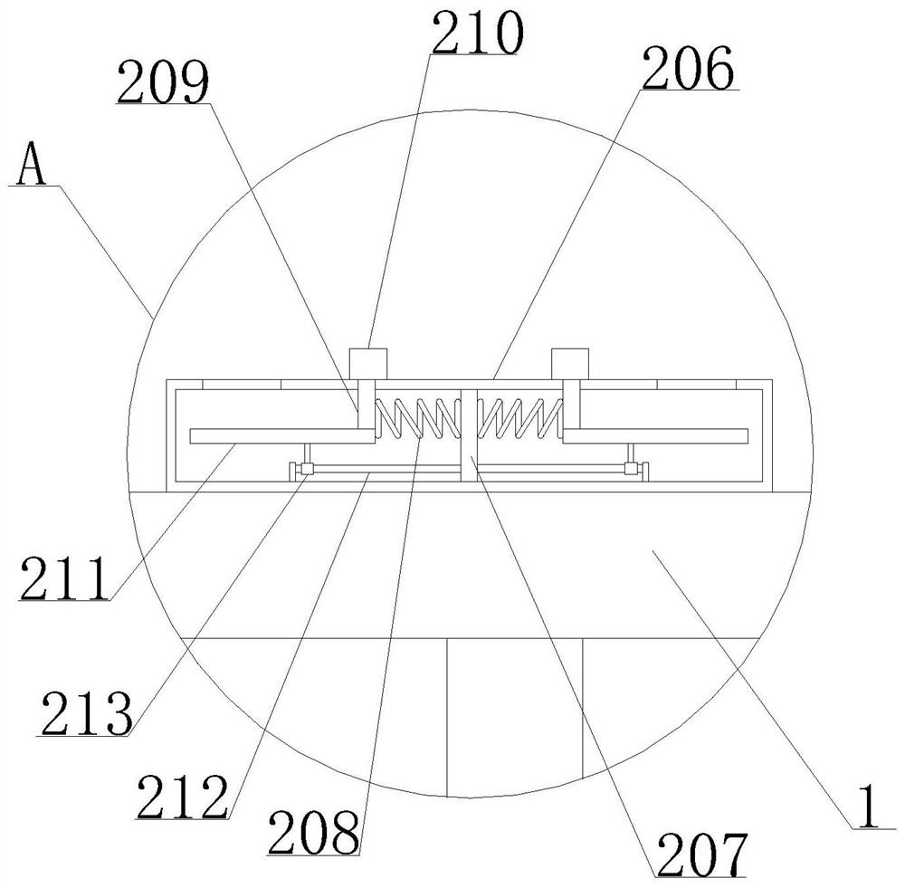
[0030] The sliding cover mechanism 2 includes a slide rail 201, and both sides of the box body 1 are equipped with a slide rail 201, and the inside of the slide rail 201 is slidably installed with a cover plate body 202, and bo...

Embodiment 2

[0041] Through the cross-shaped projection 708 provided at the opposite end of the forward screw 702 and the reverse screw 703, and the clamp rod 709 and the knob 710 on the surface of the cross-shaped projection 708, the device can turn the knob 710 when it is not necessary to clean the dust. Pulling out together with the clamping rod 709 prevents accidental touch from causing damage to the circuit, thereby ensuring the performance and service life of the device, and its structure is simple and easy to operate.

Embodiment 3

[0043] The components inside the box body 1 are directly installed on the surface of the mounting plate 4, one end of the circuit of the components is connected to the components, and the other end is connected to the electrical appliance through the through hole inside the board 6 and the through hole inside the cover body 202. This connection method does not need to pull out the connecting line in the process of dust cleaning, the cover body 202 can be opened directly, and the installation plate 4 can be pushed out by the adjustment mechanism 7 to clean up, thereby avoiding the common use of set-top boxes. It is troublesome to pull out the connection line during internal cleaning.

[0044] Working principle: The components inside the box body 1 are directly installed on the surface of the mounting plate 4, one end of the circuit of the components is connected to the components, and the other end passes through the through holes inside the board 6 and the through holes inside ...


PUM


Abstract

The invention discloses an intelligent set top box with a network camera. The intelligent set top box comprises a box body, wherein two sets of sliding cover mechanisms are symmetrically arranged on the left side and the right side of the box body, heat dissipation openings are formed in the front face and the back face of the box body, two sets of installation plates are symmetrically arranged in the box body, fixing frames are installed on the opposite sides of the two sets of installation plates, and passing plates are installed at the ends of the fixing frames. According to the set top box, a common set top box is improved, a circuit connected with the set top box does not need to be pulled out when dust removal needs to be carried out, dust removal operation can be carried out only by opening a cover plate body and rotating a forward screw and a reverse screw to push out the installation plates through movable rods, so that the installation plates and components on the surface of the installation plates are exposed, and the dust removal efficiency is improved; and through the arrangement of the sliding cover mechanisms, the set top box can well protect internal components, and meanwhile, when dust removal operation needs to be carried out, the cover plate body is convenient to open.

Description

technical field [0001] The invention relates to the technical field of set-top boxes, in particular to an intelligent set-top box with a network camera. Background technique [0002] A digital video converter box, commonly called a set-top box or set-top box, is a device that connects a television to an external signal source. It can convert the compressed digital signal into TV content and display it on the TV. Signals can come from cable, satellite dishes, broadband networks, and terrestrial broadcasts. The content received by the set-top box is to be able to receive digital content, including electronic program guides, Internet web pages, etc., in addition to the images and sounds that can be provided by analog TV. It enables users to watch digital TV programs on existing TV sets, and conduct interactive digital entertainment, education and commercial activities through the network. In recent years, with the development of broadband networks, Internet applications have ...

Claims


Application Information

Patent Timeline
Patent Type & Authority Applications(China)
IPC IPC(8): H04N21/41
CPCH04N21/41
Inventor 陈信丰
Owner 湖南省驰维智能科技有限公司
Why Eureka
Try Eureka