Separated disinfection tank structure based on gastroenterology department endoscope

A gastroenterology, disinfection tank technology, applied in the field of medical devices, can solve the problems of low disinfection efficiency, troublesome disinfection operation, etc.

Pending Publication Date: 2021-07-30
十堰市人民医院(湖北医药学院附属人民医院)
View PDF7 Cites 0 Cited by
  • Summary
  • Abstract
  • Description
  • Claims
  • Application Information

AI Technical Summary

Problems solved by technology

[0005] The object of the present invention is to provide a kind of structure based on the separated disinfection tank of gastroenterology endoscope, to solve the problem that the existing disinfection device proposed in the above-mentioned background technology n

Method used


Image

  • Separated disinfection tank structure based on gastroenterology department endoscope
  • Separated disinfection tank structure based on gastroenterology department endoscope
  • Separated disinfection tank structure based on gastroenterology department endoscope

Examples


Embodiment 1

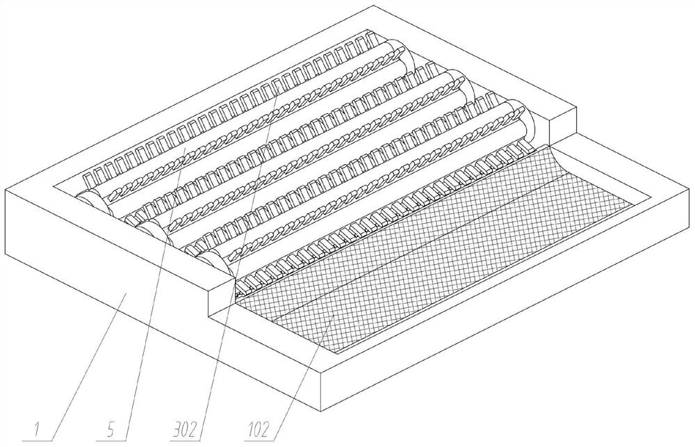
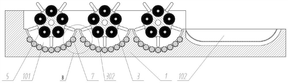
[0053] see Figure 1 to Figure 8 , an embodiment provided by the present invention: a separated disinfection tank structure based on gastroenterology endoscope, including a disinfection tank main body 1;

[0054] The circulation driving part 2, the circulation driving part 2 is fixedly connected to the rear part of the disinfection tank main body 1;

[0055] Circulation mechanism, the circulation mechanism is arranged on the inner side of the upper part of the disinfection tank main body 1;

[0056] The cleaning driver 4 is fixedly connected to the rear of the disinfection tank main body 1;

[0057] Cleaning mechanism, the cleaning mechanism is arranged on the upper part of the disinfection tank main body 1;

[0058] Rotary drive 6, the rotary drive 6 is fixedly connected to the rear of the disinfection tank main body 1;

[0059] The rotation mechanism is arranged on the inner side of the upper part of the disinfection tank main body 1 .

[0060] Further, the disinfection ta...

Embodiment 2

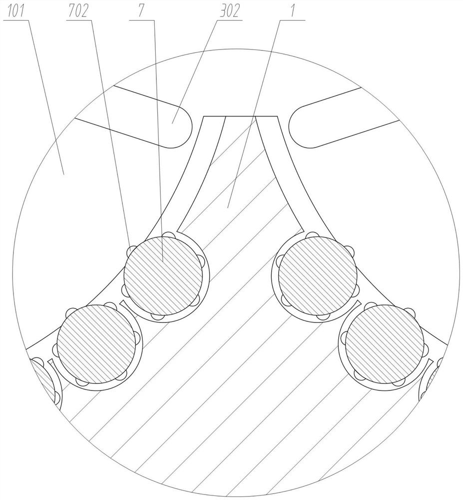
[0086] Another embodiment provided by the present invention: a separated disinfection tank structure based on gastroenterology endoscope, including a disinfection tank main body 1, a cleaning and disinfection tank 101, a collection and storage tank 102, a circulation drive part 2, a circulation active transmission part 201, Circulation operation part 3, circulation co-movement transmission part 301, circulation toggle part 302, cleaning drive part 4, cleaning part 5, cleaning driven gear 501, rotation drive part 6, rotation operation part 7, rotation co-movement transmission part 701, Rotate the friction point 702, clean the intermediate transmission part 8, clean the co-moving transmission part 801, and clean the driving gear 802;

[0087] The difference between the second embodiment and the first embodiment is that the cleaning synchronous transmission part 801 is a transmission sprocket, and the circulation active transmission part 201 and the circulation co-operation transm...


PUM


Abstract

The invention discloses a separated disinfection tank structure based on a gastroenterology department endoscope, relates to the technical field of medical instruments. The problems that when an existing disinfection device is used, the endoscope needs to be disinfected in all disinfection cavities in sequence and need to be brushed at multiple angles in the disinfection process, the disinfection operation is troublesome, and the disinfection efficiency is low are solved. The separated disinfection tank structure comprises: disinfection tank main bodies; a circulation driving part fixedly connected to the rear parts of the disinfection tank main bodies; and a circulation mechanism arranged on the inner side of the upper part of the disinfection tank main bodies. Sequential circulation of the endoscope in disinfection tanks is achieved, multi-stage cleaning and disinfecting are achieved, meanwhile, the endoscope can be brushed, the cleaning and disinfecting effect is improved, rotation of the endoscope in the disinfecting tanks is achieved, multi-angle cleaning and disinfecting are conducted, automatic draining of the endoscope can be achieved, the cleaning and disinfecting effect is improved, meanwhile, using is convenient, operation is easy, and the cleaning and disinfecting efficiency can be greatly improved.

Description

technical field [0001] The invention relates to the technical field of medical devices, in particular to a structure of a separate disinfection tank based on gastroenterology endoscope. Background technique [0002] Various endoscopes are often used in gastroenterology to check the health status of the digestive tract through the endoscope. The endoscope is widely used for its intuitive inspection and good diagnosis effect. After the endoscope is used, it is necessary to check the endoscope. Carry out cleaning and disinfection to ensure the safety of the next use. During disinfection, it needs to be disinfected through a disinfection tank. [0003] For example, the application number: CN201910032237.0 The present invention discloses an endoscope disinfection machine, including a cabinet body, an initial washing chamber, an initial washing chamber cover, a top cover spray head, a cleaning tube, an endoscope fixing frame, a drying chamber, and a drying chamber Cover, top cove...

Claims


Application Information

Patent Timeline
IPC IPC(8): A61L2/18A61L2/26A61B90/70
CPCA61L2/18A61L2/26A61B90/70A61B2090/701A61L2202/24A61L2202/17A61L2202/122
Inventor 徐艳赵丽
Owner 十堰市人民医院(湖北医药学院附属人民医院)
Why Eureka
Try Eureka