
Rotatable multi-degree-of-freedom motion platform

A motion platform and degree of freedom technology, applied in the field of motion platforms, can solve problems such as short life, high mechanical noise, and high manufacturing cost

Pending Publication Date: 2021-07-30
XIAN VIRTUAL RIDING TECH CO LTD +1
View PDF8 Cites 2 Cited by
  • Summary
  • Abstract
  • Description
  • Claims
  • Application Information

AI Technical Summary

Problems solved by technology

[0008] The purpose of the present invention is to solve the problems of the existing mounting platform itself, such as large volume, short life, high manufacturing cost, and large mechanical noise, and provide a rotatable multi-degree-of-freedom motion platform

Method used


Image

  • Rotatable multi-degree-of-freedom motion platform
  • Rotatable multi-degree-of-freedom motion platform
  • Rotatable multi-degree-of-freedom motion platform

Examples


Embodiment 1

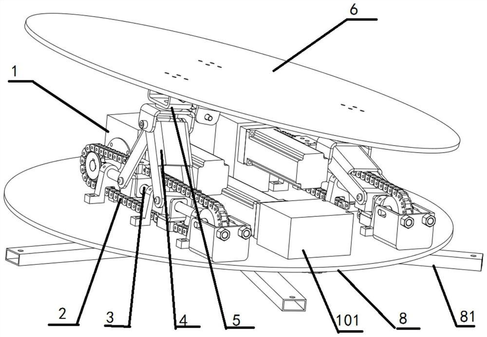
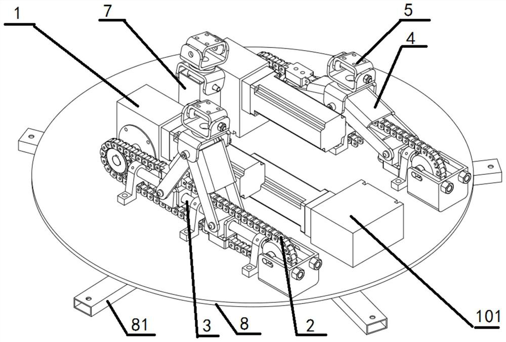
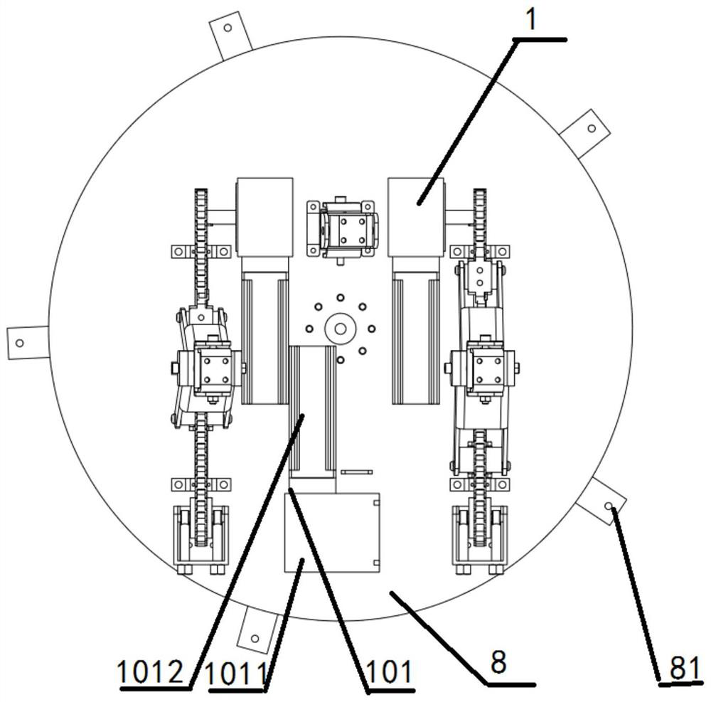
[0059] A rotatable multi-degree-of-freedom motion platform, such as figure 1 As shown, it includes a lifting support unit and an installation platform 6 . Such as figure 2 , image 3 As shown, the lifting support unit includes two lifting units and one supporting unit, and the height of the supporting unit is the middle value between the highest position and the lowest position of the lifting unit. Two lifting units and one supporting unit form three-point support for the installation platform 6, improving the stability of the entire motion platform.

[0060] The lifting unit is used to adjust the level of the entire motion platform. Such as Figure 4 to Figure 6 As shown, the lifting unit includes a first motor drive assembly 1 , a chain transmission assembly 2 , a sliding assembly 3 , a lifting assembly 4 and a universal joint 5 .

[0061] The first motor drive assembly 1 includes a first drive motor 11 and a first reducer 12 , the first drive motor 11 provides power f...

Embodiment 2

[0086] A rotatable multi-degree-of-freedom motion platform, such as figure 1 As shown, it includes a lifting support unit and an installation platform 6 . Such as Figure 9 , Figure 10 As shown, the difference from Embodiment 1 is that the lifting support unit only includes three lifting units, and the three lifting units are evenly distributed along the circumferential direction.

[0087] The lifting unit in embodiment 2 is exactly the same as embodiment 1.

[0088] The base in embodiment 2 is exactly the same as embodiment 1.

[0089] The movement process of the single lifting unit and the rotating unit 10 in the second embodiment is the same as that in the first embodiment.


PUM


Abstract

The invention relates to a motion platform, in particular to a rotatable multi-degree-of-freedom motion platform, and solves the problems that existing installation platforms are large in size, short in service life, high in manufacturing cost and large in mechanical noise. The motion platform comprises a lifting supporting unit and a mounting platform. The lifting supporting unit comprises at least two lifting units and one supporting unit or at least three lifting units. The lifting unit comprises a first motor driving assembly, a chain transmission assembly, a sliding assembly, a lifting assembly and a universal joint. The chain transmission assembly comprises a driving gear, a driven gear, a traction chain and a gear mounting seat. The sliding assembly comprises at least two supporting seats, a sliding rail supported between the at least two supporting seats, a first sliding block assembly and a second sliding block assembly, wherein the first sliding block assembly and the second sliding block assembly slide on the sliding rail. The lifting assembly comprises a first supporting frame and a second supporting frame which are of a H-shaped structure. The supporting unit comprises a universal joint and a stand column hinged to the base.

Description

technical field [0001] The invention relates to a motion platform, in particular to a rotatable multi-degree-of-freedom motion platform. Background technique [0002] Motion platform is a device that can simulate the motion state of manned equipment, such as simulating cars, ships, aircraft, etc., and has been widely used in theaters, games, entertainment venues and other fields. The object has six degrees of freedom in space, that is, the degree of freedom of movement along the three rectangular coordinate axes of x, y, and z and the degree of freedom of rotation around these three coordinate axes. The combination of different degrees of freedom can simulate different manned equipment The state of motion; in order to achieve such motion, the motion simulator is usually installed on some form of support surface or platform, and there are a series of power units under the support surface or platform to realize the motion. [0003] Existing multi-freedom motion platform also ...

Claims


Application Information

Patent Timeline
IPC IPC(8): A63G31/02A63G31/16F16M11/20
CPCA63G31/02A63G31/16F16M11/20
Inventor 钟伟刘恒科
Owner XIAN VIRTUAL RIDING TECH CO LTD
Learn More