
Multi-surface detection equipment

A surface detection and equipment technology, applied in the field of multi-surface detection equipment, can solve the problems of low work efficiency, high labor cost, large floor area, etc., and achieve high detection and transfer efficiency, high stability and reliability, and automation high effect

Active Publication Date: 2021-07-30
SUZHOU DINNAR TECH FOR AUTOMATION CO LTD
View PDF11 Cites 4 Cited by
  • Summary
  • Abstract
  • Description
  • Claims
  • Application Information

AI Technical Summary

Problems solved by technology

[0004] However, during use, there are the following problems: 1) By setting several adjustable suction nozzles on the turntable transfer device to change the position of the product and carry out material delivery, the larger volume of the turntable transfer device results in a smaller overall volume of the device. Large size, large footprint, and high cost; 2) By setting up CCD camera components with different detection focal lengths for detection, only the appearance of the side and top of the product can be detected during the detection process, and the thickness and curvature of the product cannot be determined. 3) Although there is a tray with defective appearance, it is impossible to classify and recycle the defective products according to specific defects. If the defective products need to be classified manually, it is necessary , the labor cost is large, and the work efficiency is low; 4) only a single product can be tested sequentially during the test, and multiple products cannot be tested at the same time, and the work efficiency is low

Method used


Image

  • Multi-surface detection equipment
  • Multi-surface detection equipment
  • Multi-surface detection equipment

Examples


Embodiment 1

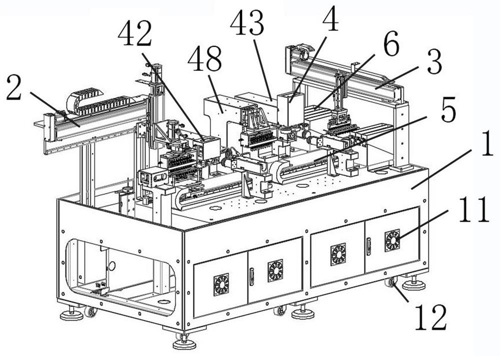
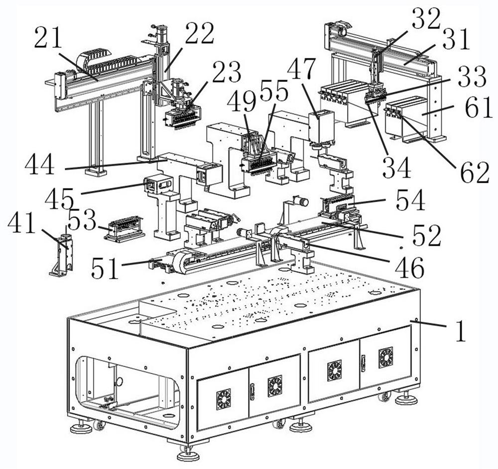
[0065] see figure 1 and figure 2 , a multi-faceted detection equipment, comprising a chassis 1, a first transport module 2, a second transport module 3, a detection device 4, a transfer module 5, a distribution box 6 and a control system;

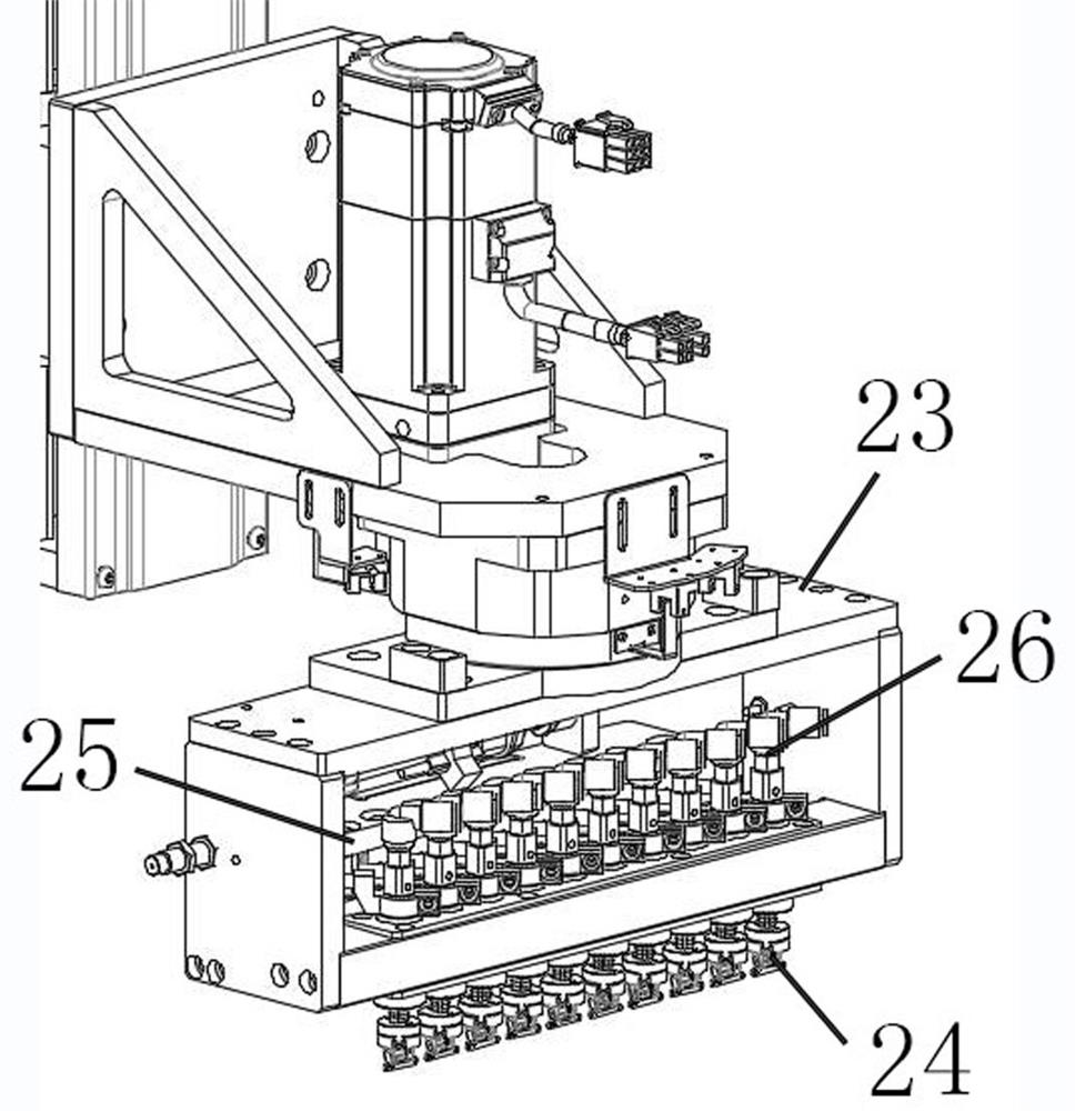
[0066] The first handling module 2 includes a first lateral movement device 21 , a first longitudinal movement device 22 disposed on the first transverse movement device 21 and a first suction device 23 disposed on the first longitudinal movement device 22 , Several rotary suction heads 24 are arranged in the first suction device 23;

[0067] The second handling module 3 includes a second lateral movement device 31 , a second longitudinal movement device 32 disposed on the second transverse movement device 31 and a second suction device 33 disposed on the second longitudinal movement device 32 , Several suction heads 34 are arranged in the second suction device;

[0068] The transfer module 5 includes a first transfer device 51 and a se...

Embodiment 2

[0118] This embodiment is carried out on the basis of the first embodiment above, and the similarities with the first embodiment will not be repeated.

[0119] In this embodiment, the first detection component is disposed around the second transfer device, and the second detection component is disposed around the first transfer device.

[0120]Further, the first detection component includes two 3D side cameras and a 3D top camera, the 3D top camera is located above the second transfer device, and the two 3D side cameras are respectively located The two adjacent sides of the second transfer device; the second detection component includes two 2D side cameras and a 2D top camera; the 2D top camera is located above the first transfer device, so The 2D side cameras are located on opposite sides of the first transfer device.

[0121] Further, when the first material suction device transfers on the first lateral moving device, the bottom surface camera takes pictures; when the first...


PUM


Abstract

The invention discloses multi-surface detection equipment which comprises a case, a first carrying module, a second carrying module, a detection device, a transfer module, a material distribution box and a control system. The first carrying module comprises a first material suction device, the second carrying module comprises a second material suction device, the transfer module comprises a first transferring device and a second transferring device, the first transferring device is provided with a first bearing seat, the second transferring device is provided with a second bearing seat, a third material suction device is arranged between the first transferring device and the second transferring device, and the detection device comprises a bottom face camera, a first detection assembly and a second detection assembly. The whole operation process of the multi-surface detection equipment is smooth without pause, and the automation degree is high; the bottom camera, the first detection assembly and the second detection assembly are arranged to carry out 2D and 3D detection on multiple aspects and multiple sizes of products, and the detection degree is higher; and the multiple products can be transferred and detected at the same time, and the detecting and transferring efficiency is higher.

Description

technical field [0001] The invention relates to the technical field of mechanical equipment, in particular to a multi-face detection equipment. Background technique [0002] At present, in the precision parts industry, the processing accuracy of the products is high, which requires multi-dimensional and multi-directional measurement and control of the parts before and after the processing of the products; due to the use of manual naked eye detection, there will be large errors , the efficiency is low, and at the same time, when the product is small in size or irregular in shape, manual inspection is easy to miss. At present, the processing and inspection process usually uses a single imager to inspect the workpiece, but the existing imager can only measure the size of a single side, and then manually switch after the measurement. When it comes to mass inspection, the labor intensity of the staff is relatively high. High, the detection efficiency is low, and the production c...

Claims


Application Information

Patent Timeline
Patent Type & Authority Applications(China)
IPC IPC(8): B07C5/00B07C5/10B07C5/02B07C5/36B07C5/38
CPCB07C5/00B07C5/02B07C5/10B07C5/362B07C5/38
Inventor 秦应化刘传磊刘奇
Owner SUZHOU DINNAR TECH FOR AUTOMATION CO LTD
Learn More